4. Technical Basics 8 - Decibels - Circuit Symbols
4.41 Decibels
- Recall the formulae for decibel voltage and power ratios.
- Calculate the gain or loss in decibels of any two voltage or power levels.
Decibels
Decibels, for some reason, seem to be the most misunderstood and disliked measurement units by amateurs, technicians and engineers although the unit is used in specifications and handbooks for many items of equipment.
Eons ago man crept through the jungle listening for sounds indicating something to eat or sounds that indicated something that wanted to eat him. His ears could distinguish quite faint sounds, they had to or he’d starve, or find himself stopping something else’s starvation. There were also very loud sounds like animals bellowing, trees falling, thunder etc. To avoid overloading the information section of the brain the volume scale of sounds was compressed. A sound with twice the power, or energy, of another didn’t sound twice as loud and it still doesn’t.
Very early in the development of amplifiers it was realised when comparing output powers the scale used needed to match mans non-linear hearing.
For a noise to sound twice as loud to the human ear it must have ten times the energy or power and to sound twice as loud again the power must increase ten times again (102) and again to seem twice as loud again the power must be increased by ten times again, or 103. One thousand times increase in power on the original sound to make it sound eight times as loud.
The convenient unit to use is the index of ten called a Bel (named after Alexander Graham Bell).
The Bel (B) is a unit of comparison and we use it with sound levels, to compare voltage, current and power levels.
In mathematical terms the Bel is:
B = Log (P1/P2)
where P1 and P2 are the power levels to be compared.
Logarithms (Logs)
The logarithms that we are concerned with are common logarithms to the base 10. In this manual whenever the term ‘log’ is used it should be taken to mean the ‘common logarithm to the base ten’. In this sense the log of a number is the power or index to which ten must be raised to get the number. In other words the log of 100 is 2; ten must be multiplied by itself twice to give one hundred; 102 = 100.
The log of 10000 is 4; 104 = 10000.
The common log of a number between 1 and 10 is somewhere between 0 and 1.
The common log of a number between 10 and 100 is between 1 and 2; and so on.
The opposite of a logarithm is an anti-logarithm.
Bel and deci-Bel
The Bel is a fairly large unit and it is more convenient to a deci-Bel (dB) which is one tenth of a Bel.
For the formulae above to give a result in decibels it becomes
dB = 10log(P1/P2) (This is the formula you need to know)
Where P1 is the power out and P2 is the power in.
Example:
An Amplifier is supplied with 50W and outputs 150W, what is the gain in dB.
dB = 10log (P1/P2)
= 10log (150/50)
= 10log 3
= 4.77dB
If a circuit has a loss then it can be expressed as a –dB.
Example:
A filter causes an attenuation of a signal from 50mW to 40mW. What is its gain/loss?
dB = 10log (P1/P2)
= 10log (40/50)
= 10log (0∙8)
= −0∙969dB gain or 0∙969dB loss
Because the decibel is a comparison between two levels it does not matter whether we look at a change from 2mW to 20mW or 2kW to 20kW the amount of change is the same. In both cases the gain is ten times or 10dB.
It may be necessary to calculate the output power given the dB increase so the formulae needs to be transposed. This will result in:
P1/P2 = antilog (dB/10)
- What is the output of an amplifier with an input of 4W and a gain of 6dB?
P1/P2 = antilog (6/10)
P1/4 = 3∙98
P1 = 3∙98*4
P1 = 15∙9W
What is the power supplied to an amplifier with a gain of 12dB and output power of 32W?
P1/P2 = antilog (12/10)
32/P2 = 15∙84
1/P2 = 15∙84/32
P2 = 32/15.84
P2 = 2W
Decibels with Voltage and Current
By the power formulae learnt earlier we know that power equals I2R or V2 / I.
This means that when comparing voltages and currents in decibels the formulae must be modified to
20log (V1/V2).
Where V1 is voltage out and V2 is voltage in.
or 20log (I1/I2).
Where I1 is current out and I2 is current in.
eg If the input to an amplifier is 2V and the output has a signal level of 50V, what is the voltage gain in decibels?
dB = 20log (V1/V2)
= 20log (50/2)
= 20log 25
= 27.95dB
Where the voltage and a gain is given the formula is rearranged to read:
V1/V2 = antilog (gain/20) or I1/I2 = antilog (gain/20)
Eg If a circuit has a gain of 12dB and the output current is 200mA what is the input current?
I1/I2 = antilog (dB/20)
200/I2= antilog (12/20)
200/12= 3·98
1/12 = 3.98/200
I2 = 200/3.98
I2 = 50.25mA
Decibels Without a Calculator
If two facts are remembered then many decibel calculations do not require a calculator.
Firstly. Every 3dB indicates a doubling of power.
If an amplifier has a 3W input and a 6W output it is obvious that the power has doubled, the increase is 3dB.
Similarly if the increase is from 3W to 12W, the input power has been doubled (3*2=6) and then doubled again (6*2=12). Each doubling of power is 3dB so the total increase is 6dB (3*2=6).
With an increase from 3W to 24W the 3 has been doubled to 6; doubled again to 12; and doubled again to 24W. Each doubling is a 3dB increase so doubling the power three times is a 9dB gain.
Note: The doubling is compounded. ie 3 doubled is 6; then 6 is doubled to 12; and 12 is then doubled to 24.
The same works in reverse so if the power is halved there is a 3dB loss or a −3dB gain.
If 40W is reduced to 10W the initial power (40W) is halved (20W) or −3dB and then halved again (10W) or −6dB.
This can also be used to resolve an output power from an input, given a gain.
An amplifier draws 2W at its input and has a 9dB gain, what is the output power?
9dB is three by 3dB or three lots of doubling. 2W doubled is 4W and doubled again is8W and a third time is 16W.
A filter has 4W output with a loss of 3dB. What is the input?
A loss of 3dB is a half so to have an output of 4 the input must be double that or 8W.
The second fact is that every 10dB indicates an increase of ten times for power.
So if we have an input of 2W and a 10dB gain, the output is ten times the input or 20W.
A 20dB gain indicates two lots of ten times. So a 20dB gain on a 2W input is 200W. 2*10 = 20 and 20*10=200. Remember each 10dB is an increase of ten times.
An amplifier with an input of 10W and a 40dB gain would have an output of?
Four lots of ten times. 10*10 = 100; 100*10 = 1000; 1000*10 = 10000; 10000*10 = 100 000.
An output of 100 000W or 100kW
These two facts can be combined. A 13dB increase consists of 3dB and 10dB or a doubling and a ten times. So a 13dB increase on 10W can be worked as 3dB =20W (10 doubled) and then 10dB, a factor of ten, 200W. (It could be worked with the 10 first then a double 10*10=100; doubled is 200W).
An antenna is fed with 100W and has a 16dB gain What is the effective radiated power in the direction of max gain.
16dB consists of 3dB +3dB+10dB, or a double, another double and a ten.
100*2=200; 200*2=400; 400*10=4000W
NOTE: The above are for power calculations only
Voltage and Current Calculations
When calculating Voltage or Current gains/losses in terms of decibels 6dB must be used for every doubling and 20dB for every increase of ten.
This is because, as seen earlier, Voltage or Current relationship to power is a multiplication of these units (P =VI).
Example:
A voltage of 12V is fed to a circuit and the output is 240V what is the dB gain?
(Because we are dealing with Voltage a double is 6dB and ten times is 20dB)
12 doubled is 24 = 6dB
24*10 is 240 = 20dB
Gain = 26dB
A amplifier has an input voltage of 25V and a gain of 32dB. What is the output voltage.
32 consists of 6+6+20. (Two doubles and a ten times)
25V doubled = 50V. 50V doubled is 100V. ten times 100 is 1000V
Output is 1kV (1000V)
Absolute Measurements using Decibels
So far we have seen that decibels are a ratio or comparison between two items. However there are some related units that can be used with decibels to refer to absolute values. To do this a reference to use as a comparison must be given. In this way we can specify a unit for comparison such as a Watt. Thus giving a unit known as dBW.
In this way a unit such as 3dBW means 3dB above 1 Watt and −3dB is 3dB below 1 Watt.
This form of specification can be done with almost any unit of power, giving dBm (referenced to a millliwatt), dBμW (referenced to a microwatt), etc. The most usual is the dBm.
As a formula
dBm = 10log(P/1mW)
Where P is the power out
Example:
What is the power of a 50W transmitter expressed in dBm?
dBm = 10 log (P/1mW)
= 10 log (50/1E−3)
= 10 log 50000
= 46∙98dBm
Other absolute decibel measurements are used for antennas.
dBi is used to express antenna gain compared to an isotropic antenna.
dBd is used to express antenna gain compared to a dipole antenna.
4.42 Mains power supplies
- Identify the circuit diagrams and characteristics of half wave, full wave and bridge rectifier circuits and associated smoothing circuits.
Rectification
The Half Wave Rectifier
A half wave rectifier uses one diode to produce a pulsating DC as shown in the diagram below. With the diode connected as shown, it will only conduct on the positive half cycles of the AC waveform. During the negative half cycles of the AC waveform the diode will be reverse biased, and no current will flow.
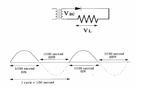
The output pulse from a half wave rectifier is at the same frequency as the input AC and is known as the ripple frequency. The average DC voltage in this circuit is 0×45VAC. Half wave rectifiers are rarely used due to their inefficiency and the inefficient use of the transformer.
The Full Wave Rectifier
Full wave rectification can be accomplished using two diodes and a centre tapped transformer.
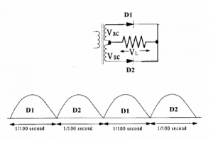
With the two diodes operating on opposite half cycles of the input we have a pulsating output with a ripple that is double the input frequency. For an AC source that has a frequency of 50 Hz, the ripple frequency will be 100 Hz. The transformer must be exactly tapped so the voltage in the D1 side of the circuit is the same as in the D2 side.
The average DC will be 0×9VAC . It is important to note that the diodes in the full wave rectifier must have a PIV of twice the peak value of VAC
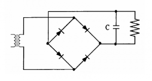
The Bridge Rectifier
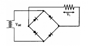
The bridge rectifier is a full wave rectifier and its output characteristics are the same as the full wave rectifier previously shown. It has two advantages over the previous example.
A centre tapped transformer is not required.
The PIV of the diodes is half of that required for the centre tapped transformer.
Equalising Resistors
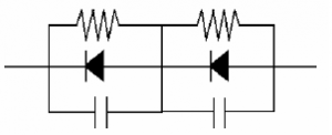
In many high voltage power supplies rectifier diodes are often placed in series to increase the peak inverse voltage rating. If a rectifier diode has a PIV of 150V then two connected in series will share the reverse voltage and have a total PIV of 300V. More diodes may be placed in series to further increase the PIV. In this case it is important to ensure that the PIV is equally shared or one of the diodes may well exceed its maximum rating and destroy all the diodes in the string. This is done by placing resistors in parallel with the diodes.
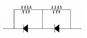
The voltage drops across the resistors will ensure that the PIV across each diode will be roughly the same.
Transient Protection Capacitors
Power supplies, particularly high voltage supplies, are prone to producing high voltage spikes (transients), caused by the inductive effects of the transformer secondary. These very short, high voltage spikes can easily overload the diodes and destroy the rectifier. To counter these spikes capacitors may be connected across the diodes. The capacitors will absorb the spikes and protect the diodes.
Output Smoothing
In all of the rectifiers described here the ripple frequency will be either the input frequency (half wave) or double the input frequency (full wave). Pulsating DC is not suitable for supplying most equipment designed to operate on a DC supply. The ripple must be smoothed out to provide a current which is close to, if not quite pure, DC as a battery would provide. This requires a circuit that smooths or filters the ripple
The simplest way of smoothing ‘rough’ DC is to connect a capacitor in parallel with the load.
Capacitor Input Filter
The capacitor stores the energy during the pulses and discharges as the peak falls below the capacitor charge. This will create a more even supply although there is still a ripple present.
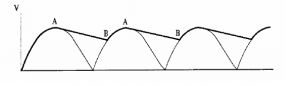
In a half wave rectifier the gaps between pulses will require the capacitor to discharge more to fill the pulses between the gaps so the ripple will be greater and the average voltage lower than with a full wave rectifier.
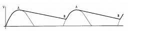
The smoothing may be increased by a larger capacitor but then the Peak Diode Current will increase so the diodes may have to have a higher forward current rating.
4.43
- Understand the need for rectifier diodes to have a sufficient peak inverse voltage (PIV) rating and be able to calculate the PIV in diode / capacitor circuits.
PIV
Rectification is the action of converting AC to DC. This is commonly done by means of a diode which allows current to only flow in one direction. Silicon diodes are commonly used and the rating can vary from 400V 1A to 1000V 200A or larger. The current rating is the maximum RMS continuous forward current. The voltage rating is the maximum peak inverse voltage ( PIV ).
NOTE – AC supplies are usually expressed in RMS.
Peak is 1×414 * RMS therefore the PIV must be at least 1×414 time higher than the supply voltage.
4.44
- Understand the function of stabilising circuits and identify Zener diode / pass transistor and switching / switched mode stabilizing circuits. Identify typical circuit configurations for linear and switching power supplies and DC to AC converters or inverters.
Power Supply Regulation
A perfect power supply would supply the prescribed voltage regardless of the load placed on it, provided it is not overloaded. Unfortunately we don’t live in a perfect world and component losses in power supplies cause the output voltage to fall as the current increases.
If the voltage drop is large (percentage wise) the power supply is said to have poor regulation. In practice the power supplies mentioned could be expected to have a regulation of 10~30%. Another cause of variation is the input voltage variation from the mains which can be up to 10% and cause a corresponding 10% variation in output.
Much of our equipment is sensitive to supply voltage variations. Output transmitter power, oscillator frequencies and transistor biasing can all be affected by input voltage. It is important to have a supply voltage as constant as possible.
One example of regulation has already been discussed under diodes, this is the zener diode regulator.
Solid State Regulators
These are also known as three-terminal regulators. These IC’s provide an accurately regulated output with a wide range of input voltages and loads. They are internally protected against overload and typically have output voltages ranging from 5V to 15V and can provide currents up to 3A.
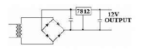
The minimum input has to be at least 2.5V above the output voltage while the maximum input voltage would be approx 30V.
Many of these regulators are 78xx series where xx indicates the output voltage.
Series Pass Transistor
In cases where the above circuit will not supply sufficient current to the output circuit a transistor is placed in a circuit around the regulator IC.
![]()
Here, Q1, a PNP power transistor allows an output current of up to five amps to be drawn. For currents below about 60 mA there will not be sufficient voltage drop across R1 to allow Q1 to start conducting and IC1 will function on its own. When the emitter base voltage of Q1 reaches about 0·6 Volts, Q1 will provide a high current path to the load. The action of the regulator maintains the output voltage constant at 5 Volts.
Solid State Power Supplies
Solid state power supplies can be divided into two categories, linear and switched.
The circuit above with the series pass transistor is an example of a linear supply.
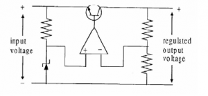
In this circuit a zener diode gives the reference voltage to the error amplifier which compares the reference with the input on its other leg and controls the series pass transistor to eliminate any error in the compared voltages.
In a switched supply the switching regulator turns the transistor on/off very rapidly to produce a square wave output which is then smoothed by the choke/capacitor. The transistors duty cycle (on/off ratio) is controlled by the PWM IC which senses the voltage at the load terminals.
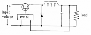
Switching regulators have a higher efficiency (less heat loss), are smaller and lighter than linear regulators, but have a slower response to variations in the load are more complex and more costly.
They are often RF noisy and may require shielding when used in a Shack.
4.45 Circuit symbols
- Identify the circuit symbols commonly used for the devices encountered in all sections of this syllabus.
Circuit symbols
some examples of symbols
Resistors
It is very common for potentiometer and rheostat symbols to be used for many types of variable resistors, including trimmers.
-

ANSI-style symbols:
(a) resistor,
(b) rheostat (variable resistor),
(c) potentiometer
-

IEC-style symbols:
(a) resistor,
(b) rheostat (variable resistor),
(c) potentiometer

Capacitors
-

IEC-style capacitor, general symbol

-

Capacitor, polarized (American)


-

IEC-style ganged (co-moving) variable capacitors

-

Trimmer capacitor

Diodes
Optionally, the triangle in these symbols may be filled in. There are multiple ways to draw a bridge rectifier symbol.
-

Diode (rectifier)


-

Light-emitting diode (LED)


-

Diac (may be a varistor in older schematics)


Inductors
-

Inductor with magnetic core (IEEE Std 315)

-

Ferrite bead (IEEE Std 315)

Transformers
-

Transformer with center tap on secondary winding (right side)
-

Transformer with two secondary windings (right side)
-

Zero-sequence current transformer (ZSCT) (also known as a window-type current transformer)
-

Bushing-type current transformer
-

Voltage transformer
Transistors
Unipolar
Optionally, these symbols may include a circle.[5]


-

Enhancement mode, N-channel MOSFET

-

Enhancement mode, P-channel MOSFET

Bipolar
Optionally, these symbols may include a circle.
.svg)
.svg)


Vacuum tubes

-

Vacuum tube triode

-

Vacuum tube tetrode

-

Vacuum tube pentode

Switches[edit]
-

Switch, single-pole/single-throw (SPST)
-

Switch, single-pole/double-throw (SPDT)

-

Switch, double-pole/double-throw (DPDT)

-

Pushbutton, momentary or Spring-Return, make (IEEE Std 315)

-

Pushbutton, momentary or spring-return, break (IEEE Std 315)
-

Pushbutton, momentary or spring-return, two-circuit (IEEE Std 315)

Relays
-

American-style relays, SPST, SPDT, DPST, DPDT

-

IEC relay symbol, SPDT

Lamps
-

Indicating lamp (IEEE Std 315-1975)


-

Incandescent light bulb (as an indicator)


-

Light bulb

Current limiters
-

Moulded-case circuit breaker (MCCB)


Electro-acoustic devices
-

IEC-style microphone

-

Microphone (IEEE Std 315)


-

Loudspeaker (IEEE Std 315)

Antennas

-

Loop antenna (IEEE Std 315)

Connectors

ICs
-

Operational amplifier (opamp) or comparator

.svg)
