4. Technical Basics 5 - Tuned circuits
4.22 Tuned circuits
- Understand the formula for resonant frequency and that, at resonance, XC = XL.
- Apply the formula to find values of; f, L or C from given data.
Resonance
We have seen that both capacitive reactance and inductive reactance are dependant on frequency. Inductive reactance XL increases with frequency while capacitive reactance Xc decreases with rising frequency. Therefore if we have both XL and XC in a circuit there will be one frequency at which XL = XC .
This is known as the resonant frequency (fr) and at this point the circuit is known as a tuned circuit for the given frequency.
Resonant Frequency
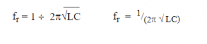
The resonant frequency of a tuned circuit (series or parallel) is given by the following formula:
Example:
The resonant frequency of a circuit containing an inductor of25nH and a capacitor of 50pF is:
fr = 1 / (2π√LC)
= 1 /( 6.283*√(25E-9*50E-12))
= 1 / (6.283*√1.25E-18)
= 1 / (6.283*1.118E-9)
= 1 / 7.024E-9
= 142 369 020.5 Hz
4.23
- Identify resonance curves for series and parallel tuned circuits.
Tuned circuits
Series Tuned Circuit
The circuit below shows a series LC circuit.
Note that we have included resistance as there is no such thing as a perfect inductor or perfect capacitor. There will always be some resistance present in the windings of the inductor and there will be losses in the dielectric of the capacitor.
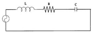
If the XL and XC are in series, at resonance the XL and XC are equal in magnitude and opposite in phase and therefore cancel each other leaving the circuit as purely resistive. If the supply frequency is moved away from the resonant frequency the impedance increases and the current falls.
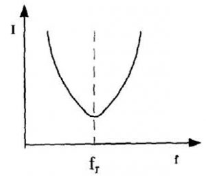
Resonance Curve for a Series Circuit
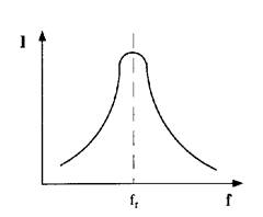
The impedance Z of a series LC circuit at resonance will be equal to the value of resistance present and the current flowing through the circuit will be at a maximum value.
In summary for a series LC circuit at resonance
Z = R and is low
I is at a maximum
Parallel Tuned Circuit
In a parallel circuit at the resonant frequency XC = XL but in this case although the reactance is equal they do not cancel each other out. It is the currents in each branch that are out of phase and cancel each other.
As the circuit moves off resonance, the reactance in one of the branches will reduce allowing some current to flow. If the frequency is reduced the reactance in the capacitive branch will increase but the reactance in the inductive branch will reduce allowing the current to flow in that side of the circuit.
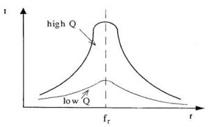
Resonance curve for a parallel Circuit
At resonance in a parallel circuit the impedance is at maximum, in theory it is infinity, however as there is always some resistance in the inductor it will only be a very high figure.
In summary, for a parallel tuned circuit at resonance
Z = High
Current is low
4.24
- Understand the concept of the magnification factor Q as applied to the voltages and currents in a resonant circuit.
- Understand and apply the formula for Q factor given circuit component values.
- Recall the definitions of the half power point and the shape factor of resonance curves.
- Recall and apply the equation for Q given the resonant frequency and the half power points on the resonance curve.
Quality Factor
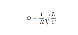
The Quality Factor (Q) of a component or circuit is a number calculated from the ratio of energy stored to the energy lost.
Q = X/R
NOTE: In this formulae X does NOT indicate a net reactance (as that will be zero in all resonant circuits) but can use either XC or XL which will be equal at resonance.
As such it is an indicator of the losses in the tuned circuit. A high Q tuned circuit will have less loss than a low Q tuned circuit.
Because the Q of a circuit depends on the amount of reactance the Q figure can be controlled by the values of components used in the circuit.
Example:
A circuit consisting of a capacitor of 60pF and 2μH inductor, with 10Ω of resistance will be resonant on approx 14∙5MHz (fr = 1 / (2π√LC) with approx 182Ω of reactance (XL = 2πfL). This gives a Q of 18∙2 (Q = X/R).
If the reactive components are replaced with a 120pF capacitor and a 1μH inductor the resonant frequency is still 14∙5MHz but the reactance is now 91∙1Ω and the Q has changed to 9∙1.
If the capacitor value were reduced (30pF) thereby requiring an increase in inductance (4μH) for the same resonant frequency (14.5MHz) the reactance is now 364∙4Ω giving a Q of 36∙44.
Half power point
It is important to recognize where a filter is considered to have significant attenuation, that is to say where on its response curve the signal is diminished enough to ignore. On power curves this is accepted to be at −3dB or where the incoming signal is reduced to half power and for this reason they are also known as half power points. Beyond this point the signal diminishes rapidly.
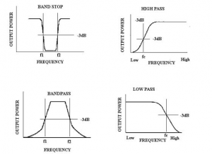
Curves showing -3dB (half-power) points.
It is also important to realise that the half power points combine with the Q of a circuit to determine its bandwidth.
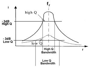
Normally a curve would be drawn showing the actual frequencies on the horizontal axis and the dB points on the vertical axis
4.25
- Understand the meaning of impedance of series and parallel tuned circuits.
- Understand the effect of damping resistors in a tuned circuit.
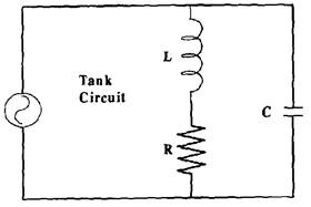
Tank circuit
A resonant parallel tuned circuit is also known as a Tank Circuit.
At resonance, it acts like a storage tank for electrical energy. The energy continually and smoothly changes between the electric field stored in the capacitor and the magnetic field stored in the inductor.
With perfect components this would keep on for ever, but the inductor and wiring will always have some resistance and the capacitor has some dielectric losses, so the energy gradually diminishes unless it is topped up from an external source.
If the oscillation is only required for a short period a resistor may be inserted into the circuit at such a value as to intentionally damp the oscillation at a given rate. This resistor is known as a ‘damping resistor’.
4.26
- Recall the equivalent circuit of a crystal. Recall that circuits using crystals may exhibit series or parallel resonance characteristics.
Crystal resonance
Any crystal will have two resonant frequencies. At one it acts in series resonance giving a low impedance and therefore high current flow and at the other it will act in parallel resonance producing a high impedance and thus low current flow.
The equivalent circuit of a crystal is a combination series parallel tuned circuit.
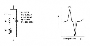
With a frequency of 100kHz the series side of the combination is at series resonance and therefore has a minimum impedance depending upon the value of the circuit resistance (RS). So at this frequency there is maximum current flow through the series circuit.
As the frequency is increased above the 100kHz the inductance reactance on the series side of the circuit increases and the capacitive reactance of C1 decreases. The series side of the circuit now has a net inductive reactance.
At about 103.5kHz the net reactance (XL – XC) on the series side will equal the reactance on C2, giving a parallel resonant circuit which will have maximum impedance therefore minimum current flow.
It is impossible to actually construct an equivalent circuit to a crystal as an inductor of the size required would have very large losses.
4.27
- Recall that voltages and circulating currents in tuned circuits can be very high and understand the implications for component rating.
Resonance Voltage/Current
At resonance level
Impedance is minimum, current is maximum, phase angle is 0°, and power factor is unity.
Voltage magnification
The quality-factor of RLC series circuit at resonance condition,
Voltage_magnification = (Voltage through L or C / Input Voltage) = (VL/V)
and
 Voltage magnification factor is calculated at different levels of supply voltage, and it’s shown in Table 3. The series RLC circuit is at resonance, the magnitudes of voltages can become larger than the supply voltage and it is displayed in Figure 4.

Figure 4. Voltage magnification as per supply voltage.
Current magnification
By means of the parallel resonant circuit, the current taken from the supply can be magnified. This type of resonance is called current resonance. Quality factor of R-L-C parallel circuit is the current magnification in the circuit at resonance.
Current_magnification = Circulating current in Xc / Current (I) from the mains (or) Ic / I
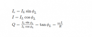
where Q is a measurement of current magnification, current at resonance = I = V / Z0, Z0 = L/RC, I = V / (L / Rc) = VRC / L.
When the parallel R-L-C circuit is at resonance, the magnitudes of the current become increasingly based on given supply voltage and it is shown in Figure 5.

Figure 5. Current Magnification as per supply voltage.
Due to the above, all components in a resonant circuit need to have appropriate voltage and current rating above supply voltage.