4. Technical Basics 3 - Inductance
4.12
- Understand the term 'self inductance' and recall that a 'back EMF' is produced as current flow changes in an inductor.
Self inductance
Induced currents only ocur when a magnetic field builds or collapses.
Lenz's law tells us that the induced current is such as to oppose the change producing it.
So the induced current will oppose the primary current when the field is building. Conversely, when the field is collapsing the current will be in the opposite direction to try to prevent the collapse.
In the first instance the induced current field will be in a sense to oppose the primary current building. In the second instance when the field is collapsing, it will be in the same direction to lessen the collapse..
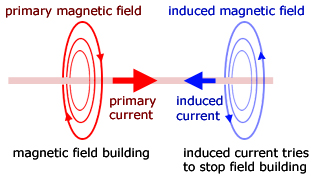
The induced current is produced by a 'back EMF' - an induced voltage proportional to minus the rate of primary current change.
![]()
![]()
where L (the inductance) is the constant of proportionality.
Rearranging to make L the subject of the equation. By making E and dI/dt unity we define the unit of self induction, the henry:

A coil has a self inductance of 1 henry (H) if the back EMF is 1 volt for a current change of 1 ampere/second.
By equating the EMF from Neumann's equation with self induction EMF a simplified expression linking the two can be formed.
![]()
Integrating between the limits of φ - 0 and I - 0 ,
![]()
![]()
Mutual Induction
Mutual induction concerns a pair of coils. A building current in one coil (the primary) produces a building magnetic field around it. This in turn induces a building current to flow in the other coil. The induced current flow is in such a direction as to produce a magnetic field direction to oppose the primary magnetic field. The magnetic fields are directed towards each other. So their total effect is reduced.
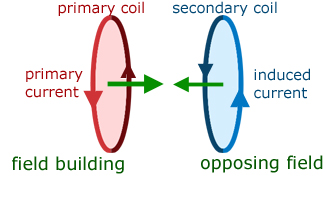
When the primary current direction is reversed its magnetic field direction is also reversed. This has the effect of making current in the secondary reverse direction together with its magnetic field direction. In this case the magnetic fields are in opposing directions.
As with self inductance, the back EMF is proportional to minus the rate of current change. However, in this case the back EMF is in the secondary coil, not and in the primary(as with self induction).
![]()
![]()
Where M (mutual inductance) is the constant of proportionality.
There is another important link between self and mutual inductance. It can be shown, assuming 100% flux linkage that,
![]()
where Lp and Ls are respectively the self inductances of primary and secondary coils.
So the back EMF Es in the secondary coil relates to the rate of current change dIp/dt in the primary.
![]()
The secondary back EMF also relates to the rate of change of flux linkage in the secondary.
![]()
Elimenating Es from these two expressions,
![]()
Integrating between the limits of φs - 0 and Ip - 0 ,
![]()
![]()
4.13
- Recall that the inductance of a coil increases with increasing number of turns, increasing coil diameter and decreasing spacing between turns.
- Understand the use of high permeability cores and slug tuning.
Factors affecting inductance
To increase the property of inductance, the conductor can be formed into a loop or coil. A coil is also called an inductor. Figure 2-3 shows a conductor formed into a coil. Current through one loop produces a magnetic field that encircles the loop in the direction as shown in figure 2-3(A). As current increases, the magnetic field expands and cuts all the loops as shown in figure 2-3(B). The current in each loop affects all other loops. The field cutting the other loop has the effect of increasing the opposition to a current change.
Figure 2-3. - Inductance.
Inductors are classified according to core type. The core is the center of the inductor just as the core of an apple is the center of an apple. The inductor is made by forming a coil of wire around a core. The core material is normally one of two basic types: soft-iron or air. An iron-core inductor and its schematic symbol (which is represented with lines across the top of it to indicate the presence of an iron core) are shown, in figure 2-4(A). The air-core inductor may be nothing more than a coil of wire, but it is usually a coil formed around a hollow form of some nonmagnetic material such as cardboard. This material serves no purpose other than to hold the shape of the coil. An air-core inductor and its schematic symbol are shown in figure 2-4(B).
Figure 2-4. - Inductor types and schematic symbols.
Factors Affecting Coil Inductance There are several physical factors which affect the inductance of a coil. They include the number of turns in the coil, the diameter of the coil, the coil length, the type of material used in the core, and the number of layers of winding in the coils.
Inductance depends entirely upon the physical construction of the circuit, and can only be measured with special laboratory instruments. Of the factors mentioned, consider first how the number of turns affects the inductance of a coil. Figure 2-5 shows two coils. Coil (A) has two turns and coil (B) has four turns. In coil (A), the flux field set up by one loop cuts one other loop. In coil (B), the flux field set up by one loop cuts three other loops. Doubling the number of turns in the coil will produce a field twice as strong, if the same current is used. A field twice as strong, cutting twice the number of turns, will induce four times the voltage. Therefore, it can be said that the inductance varies as the square of the number of turns.
Figure 2-5. - Inductance factor (turns).
The second factor is the coil diameter. In figure 2-6you can see that the coil in view B has twice the diameter of coil view A. Physically, it requires more wire to construct a coil of large diameter than one of small diameter with an equal number of turns. Therefore, more lines of force exist to induce a counter emf in the coil with the larger diameter. Actually, the inductance of a coil increases directly as the cross-sectional area of the core increases. Recall the formula for the area of a circle: A = pr2. Doubling the radius of a coil increases the inductance by a factor of four.
Figure 2-6. - Inductance factor (diameter).
The third factor that affects the inductance of a coil is the length of the coil. Figure 2-7 shows two examples of coil spacings. Coil (A) has three turns, rather widely spaced, making a relatively long coil. A coil of this type has few flux linkages, due to the greater distance between each turn. Therefore, coil (A) has a relatively low inductance. Coil (B) has closely spaced turns, making a relatively short coil. This close spacing increases the flux linkage, increasing the inductance of the coil. Doubling the length of a coil while keeping the same number of turns halves the value of inductance.
Figure 2 - 7. - Inductance factor (coil length). CLOSELY WOUND
The fourth physical factor is the type of core material used with the coil. Figure 2-8 shows two coils: Coil (A) with an air core, and coil (B) with a soft-iron core. The magnetic core of coil (B) is a better path for magnetic lines of force than is the nonmagnetic core of coil (A). The soft-iron magnetic core's high permeability has less reluctance to the magnetic flux, resulting in more magnetic lines of force. This increase in the magnetic lines of force increases the number of lines of force cutting each loop of the coil, thus increasing the inductance of the coil. It should now be apparent that the inductance of a coil increases directly as the permeability of the core material increases.
Figure 2-8. - Inductance factor (core material). SOFT-IRON CORE
Another way of increasing the inductance is to wind the coil in layers. Figure 2-9 shows three cores with different amounts of layering. The coil in figure 2-9(A) is a poor inductor compared to the others in the figure because its turns are widely spaced and there is no layering. The flux movement, indicated by the dashed arrows, does not link effectively because there is only one layer of turns. A more inductive coil is shown in figure 2-9(B). The turns are closely spaced and the wire has been wound in two layers. The two layers link each other with a greater number of flux loops during all flux movements. Note that nearly all the turns, such as X, are next to four other turns (shaded). This causes the flux linkage to be increased.
Figure 2-9. - Coils of various inductances.
A coil can be made still more inductive by winding it in three layers, as shown in figure 2-9(C). The increased number of layers (cross-sectional area) improves flux linkage even more. Note that some turns, such as Y, lie directly next to six other turns (shaded). In actual practice, layering can continue on through many more layers. The important fact to remember, however, is that the inductance of the coil increases with each layer added.
As you have seen, several factors can affect the inductance of a coil, and all of these factors are variable. Many differently constructed coils can have the same inductance. The important information to remember, however, is that inductance is dependent upon the degree of linkage between the wire conductor(s) and the electromagnetic field. In a straight length of conductor, there is very little flux linkage between one part of the conductor and another. Therefore, its inductance is extremely small. It was shown that conductors become much more inductive when they are wound into coils. This is true because there is maximum flux linkage between the conductor turns, which lie side by side in the coil.
Permeability refers to the ability of a substance to concentrate magnetic lines of force and must not be confused with permittivity which is the ability to concentrate line of electrical force.
A fero-magnetic material placed within a magnetic field will concentrate the field by pulling the lines of force closer together. If the material is placed at an angle to the normal field it can also skew or alter the direction of the field.
This effect can be used to vary the inductance in a coil by inserting a moveable core, termed a slug, into the coil. The slug is usually on a screw which allows it to be easily moved in or out of the coil. As the slug is partially removed so the concentration of magnetic force lines will affect less of the coil thus reducing the inductance.
4.14
- Understand the formula for time constant (T=L/R) in relation to the rise and fall of current in an LR circuit.
Time constant for inductance
When a current is applied to an inductor it takes some time for the current to reach its maximum value, after which it will remain in a "steady state" until some other event causes the input to change. The time taken for the current to rise to its steady state value in an LR circuit depends on:
•The resistance (R)
This is the total circuit resistance, which includes the DC resistance of the inductor (RL) itself, plus any external circuit resistance.
• The inductance of L
Which is proportional to the square of the number of turns, the cross sectional area of coil and the permeability of the core.
An Inductor opposes CHANGES in current flow
Fig. 4.5.1 The LR Time Constant
When the circuit in Fig 4.5.1 is switched on current changes rapidly from zero, this sudden change creates a rapidly expanding magnetic field around the inductor coils, and in doing so induces a voltage back into the coil. This induced voltage (called a back EMF) creates a current (the green arrowhead in the circuit diagrame) flowing in the OPPOSITE direction to the original current (the blue arrowhead in the circuit diagrame) applied by the battery.
See the Back EMF current and supply current change during the time illustrated by the video in Fig 4.5.1 The result of the sudden change voltage as the circuit switches on is that the rate of change in circuit curent, instead of causing a sudden increase in current from 0V to Maximum current increases ay a slower rate than it would in a totally resitive circuit. If the initial rate of change of current in the LR circuit were to continue in a linear fashion, the current would reach its maximum or steady "state value" in a time (T) given by:
T = L/R seconds.
- T is the TIME CONSTANT and is measured in seconds
- L is the INDUCTANCE and is measured in Henrys
- R is the TOTAL CIRCUIT RESISTANCE and is measured in Ohms.
Seconds and Henrys are usually far too large for most electronics measurements, and milli and micro units are commonly used, but remember when calculating to convert any of these sub units to seconds or Henrys for use in formulae.
The rise in current is not linear however, but follows a curved "exponential" path, and in one time constant (indicated in Fig 4.5.1 by the vertical dotted line) the current (indicated by the horizontal dotted line) will have only risen to 63.2% of its maximum (steady state) value. After two time constants it will reach 86.5%, after 3 time constants 95% and so on until it reaches 99.5% which is regarded as its maximum value after 5 time constants.
Discharge
If the circuit is switched off, current now does not immediately fall to zero, it again falls exponentially, and after one time constant period will have reached 36.8% of the previous steady state value (i.e.the steady state value -63.2%). It is considered to reach zero in five time constant periods.
The Exponential Curve
The change of current in an inductor in response to a step change in input is exponential. For a series of equal time periods, the current charges the inductor towards its maximum value, by a percentage of the remaining difference between the present and maximum values. So although this difference continues to shrink, the extra charge built up during each time period also shrinks. The outcome of this is that the current can never ever reach the maximum!
Why 63.2%?
If the current never reaches its steady state value, this presents a problem of how to measure the time taken to fully charge. This is why the idea of a time constant, (the time it takes to charge by 63.2%) is used. Why choose 63.2% when there are easier numbers such as 50% that could be used? Well 50% would be nice but would create an awkward formula with which to calculate the time taken.
Its Simple!
It so happens that using 63.2% (which is not too different from 50%) results in a nice simple formula of L/R for the inductor time constant, and CR for the capacitor time constant. This greatly simplifies calculations, and because the current will have reached 99.5% of the steady state value after 5 time constants, this is near enough in practice to consider that the maximum value has been reached.
4.15
- Understand and apply the formulae for calculating the combined values of inductors in series
Inductors in series
When inductors are connected in series, the total inductance is the sum of the individual inductors’ inductances. To understand why this is so, consider the following: the definitive measure of inductance is the amount of voltage dropped across an inductor for a given rate of current change through it.
If inductors are connected together in series (thus sharing the same current, and seeing the same rate of change in current), then the total voltage dropped as the result of a change in current will be additive with each inductor, creating a greater total voltage than either of the individual inductors alone. Greater voltage for the same rate of change in current means greater inductance.
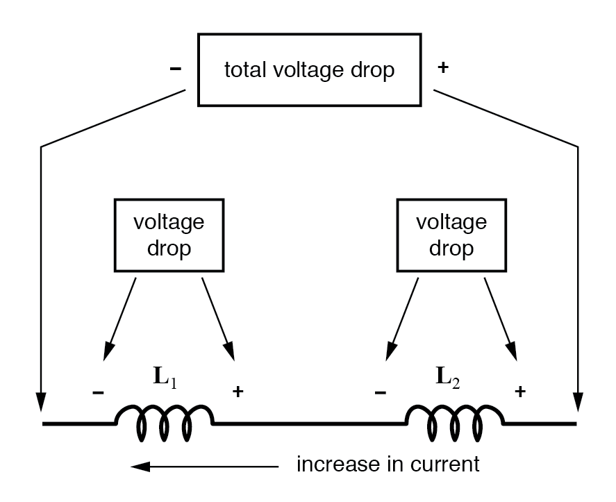
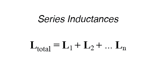
Thus, the total inductance for series inductors is more than any one of the individual inductors’ inductances. The formula for calculating the series total inductance is the same form as for calculating series resistances:
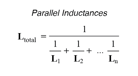
Inductors in parallel
When inductors are connected in parallel, the total inductance is less than any one of the parallel inductors’ inductances. Again, remember that the definitive measure of inductance is the amount of voltage dropped across an inductor for a given rate of current change through it.
Since the current through each parallel inductor will be a fraction of the total current, and the voltage across each parallel inductor will be equal, a change in total current will result in less voltage dropped across the parallel array than for any one of the inductors considered separately. In other words, there will be less voltage dropped across parallel inductors for a given rate of change in current than for any of those inductors considered separately, because total current divides among parallel branches.
Less voltage for the same rate of change in current means less inductance.
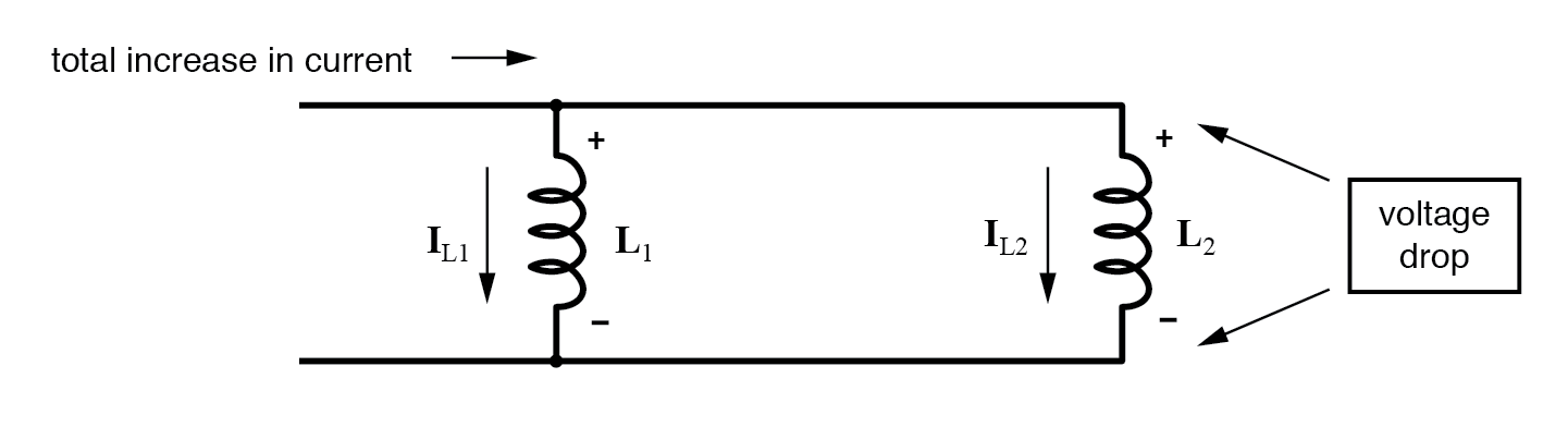
Thus, the total inductance is less than any one of the individual inductors’ inductances. The formula for calculating the parallel total inductance is the same form as for calculating parallel resistances:
Coupled inductors (optional)
Mutually Connected Inductors in Series
Now consider that inductors are connected such that magnetic field of one coil affects the other. When two or more inductors are connected in series, then the inductance of one inductor will be affected by the magnetic field produced by the other coil.
This is called mutual inductance and the coils are called “Mutually connected inductors”. This mutual inductance may increase or decrease the total inductance of the series circuit.
The factor that affects the mutual inductance of a series connected of inductors is the distance between the coils and their orientation.
The mutually connected inductors can coupled in two types
1) Cumulatively coupled or Series Aiding
2) Differentially coupled or Series opposing
Cumulatively Coupled Inductors in Series
If the magnetic fluxes produced by the inductors are in the same direction to the flow of current through them, then the coils are known as “Cumulatively coupled”.
In this series aiding or cumulative coupled circuit, the current enters or leaves the terminals of coils at any instant of time are in the same direction.
The figure below shows the connection of two inductors in series aiding arrangement.
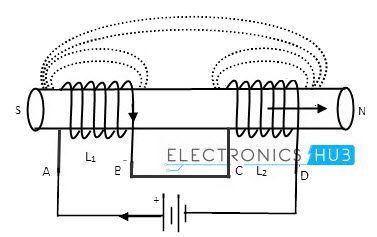
If we pass the current through the cumulatively coupled coils (between the nodes A & D) in the same direction, the voltage drop of each individual coil will affect the total inductance of the series.
Let self inductance of the coil-1 is L1, self inductance of the coil-2 is L2 and the mutual inductance is M between coil 1 and coil2.
Self induced emf in coil-1 is
e1 = – L1 di/ dt
Mutual induced emf in coil-1 due to change of current in coil-2 is
eM1 = – M di/ dt
Similarly, Self induced emf in coil-2 is
e2 = – L2 di/ dt
Mutual induced emf in coil-2 due to change of current in coil-1 is
eM2 = – M di/ dt
Therefore, total induced emf in the series aiding circuit is given as
e = – L1 di/ dt– L2 di/ dt– 2M di/ dt
= – (L1+ L2 + 2M) di/ dt
If LT is the total inductance of the circuit, the total induced emf will be equivalent to
e = – LT di/ dt
Substituting in the above equation, we get
– LT di/ dt = – (L1+ L2 + 2M) di/ dt
Therefore, LT = (L1 + L2 + 2M)
Cumulatively Coupled Inductors in Series Example
Ex: If two coils of inductance 70 mH and 30 mH are connected in series, then find the total cumulative inductance of the series connected inductors. Consider the mutual inductance of the combination of the two coils is 40 mH.
Sol:
Given that, L1 = 70 mH
L2 = 30 mH
M = 40 mH
Applying the formula for cumulatively connected inductors, LT = L1 + L2 + 2M
LT = 70 + 30 + 2 (40)
= 100 + 80
=180 mH
Therefore the cumulative inductance of the coil is 180 milli Henry.
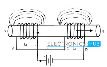
Differentially Coupled Inductors in Series
If the magnetic fluxes produced by the inductors are in the opposite direction to each other, then the coils are known as “Differentially coupled”.
In this differential coupled or series opposition connection, the current enters or leaves the terminals of coils at any instant of time are in the opposite direction.
The figure below shows the connection of two inductors in series opposition arrangement.
In differentially coupled coils, the magnetic flux fields may produce in same direction or opposite direction. Let the self inductance of the coils are L1 and L2 and the mutual inductance is M.
Here mutual inductance will be aided to each coil self inductance due to the circuit configuration.
Therefore, total induced emf in the series opposing circuit is given as
e = – L1 di/ dt– L2 di/ dt + 2M di/ dt
= – (L1+ L2 – 2M) di/ dt
If LT is the total inductance of the circuit, the total induced emf will be equivalent to
e = – LT di/ dt
Substituting in the above equation, we get
– LT di/ dt = – (L1+ L2 – 2M) di/ dt
Therefore, LT = (L1 + L2 – 2M)
Differentially Coupled Inductors in Series Example
Ex: If two coils of inductance 70 mH and 30 mH are connected in series, then find the total differential inductance of the series connected inductors. Consider the mutual inductance of the combination of the two coils is 40 mH.
Sol:
Given that, L1 = 70 mH
L2 = 30 mH
M = 40 mH
Applying the formula for differentially connected inductors, LT = L1 + L2 – 2M
LT = 70 + 30 – 2 (40)
= 100 – 80
= 20 mH
Therefore the Differential inductance of the coil is 20 milli Henry.
Summary
- An inductor is a passive element which is used in electronics circuits for storing energy as magnetic flux. Inductance is measured in Henry.
- The dissipation amount of actual power with the current flow in the circuit is called “Inductive reactance”. It is measured in ohms. XL = 2 f L
- Self inductance is the property of an electric circuit or a loop in which its own magnetic field opposes any change in current
- Mutual inductance is the ability of an inductor that causes to induce emf in another inductor placed very close to it when current in first inductor changes.
- The end to end connection of two or more inductors is called “series connection of inductors”. The formula for total inductance in series is LT = L1 + L2
- The total inductance of the series connected inductors is always greater than the largest inductor in that series.
- If the magnetic fluxes produced by the inductors are in the same direction to the flow of current through them, then the coils are known as “Cumulatively coupled”. LT = L1 + L2 + 2M
- If the magnetic fluxes produced by the inductors are in the opposite direction to each other, then the coils are known as “Differentially coupled”. LT = L1 + L2 – 2M