4. Technical Basics 2 - Capacitance
4.6
- Understand that the capacitance of a capacitor is influenced by the area and separation of the plates and the permittivity of the dielectric. Understand the formula C=KA/d.
What is a capacitor ?
A capacitor is a device used to store electrical charge and electrical energy. Capacitors are generally with two electrical conductors separated by a distance. (Note that such electrical conductors are sometimes referred to as “electrodes,” but more correctly, they are “capacitor plates.”) The space between capacitors may simply be a vacuum, and, in that case, a capacitor is then known as a “vacuum capacitor.” However, the space is usually filled with an insulating material known as a dielectric. (You will learn more about dielectrics in the sections on dielectrics later in this chapter.) The amount of storage in a capacitor is determined by a property called capacitance, which you will learn more about a bit later in this section.
Capacitors have applications ranging from filtering static from radio reception to energy storage in heart defibrillators. Typically, commercial capacitors have two conducting parts close to one another but not touching, such as those in the figure below. Most of the time, a dielectric is used between the two plates. When battery terminals are connected to an initially uncharged capacitor, the battery potential moves a small amount of charge of magnitude Q from the positive plate to the negative plate. The capacitor remains neutral overall, but with charges
and
residing on opposite plates.
Both capacitors shown here were initially uncharged before being connected to a battery. They now have charges of
and
(respectively) on their plates. (a) A parallel-plate capacitor consists of two plates of opposite charge with area A separated by distance d. (b) A rolled capacitor has a dielectric material between its two conducting sheets (plates).
A system composed of two identical parallel-conducting plates separated by a distance is called a parallel-plate capacitor (see below). The magnitude of the electrical field in the space between the parallel plates is
, where
denotes the surface charge density on one plate (recall that
is the charge Q per the surface area A). Thus, the magnitude of the field is directly proportional to Q.
Capacitors with different physical characteristics (such as shape and size of their plates) store different amounts of charge for the same applied voltage V across their plates. The capacitance C of a capacitor is defined as the ratio of the maximum charge Q that can be stored in a capacitor to the applied voltage V across its plates. In other words, capacitance is the largest amount of charge per volt that can be stored on the device:
The SI unit of capacitance is the farad (F), named after Michael Faraday (1791–1867). Since capacitance is the charge per unit voltage, one farad is one coulomb per one volt, or
By definition, a 1.0-F capacitor is able to store 1.0 C of charge (a very large amount of charge) when the potential difference between its plates is only 1.0 V. One farad is therefore a very large capacitance. Typical capacitance values range from picofarads
(
Capacitors can be produced in various shapes and sizes.
Calculating Capacitance
The capacitance of a capacitor is calculated using the formulae:
C = KA/d * 8.85E-12
Where C is the capacitance in Farads; K is the dielectric constant; A is the (overlapping) area of one plate in square metres; and d is the distance between the plates in metres. The constant
8.85E-12 is the absolute permittivity of free space.
Example.
Calculate C for an air capacitor with two plates, each with an area of 2 square metres, separated by 1 centi metre (1cm=10mm).
C = KA/d * 8∙85E-12
= 1*2 / 10E-3 * 8∙85E-12
= 200 *8∙85E-12
= 1770E-12
= 1770pF
Increasing/Reducing capacity
The capacitance of a capacitor can be increased as follows,
- Increasing the overlapping area of it’s plates
- Increasing the number of plates connected in parallel
- Decreasing the distance between the plates
- Using an insulating material with a high dielectric constant.
The value of capacitance will be reduced if,
- the overlapping area of the plates is reduced
- the number of plates connected in parallel is reduced
- the distance between the plates is increased
- the insulator has a low dielectric constant
NOTE: The area of the plates refers to the area overlap not the physical size of each plate. In most cases this is the same but, as in the tuning capacitor, it is the overlapping area that decides the capacitance not the overall size of each plate.
Dielectric
The dielectric is the material between the capacitors plates. In tuning or adjustable capacitors this is very often air but in fixed value capacitors many other substances may be used.
As seen above the material between the plates determines the capacitance of the device. As well as acting as an insulator this dielectric concentrates the electrical force lines. All dielectrics are compared to air to give them a value. This is known as the dielectric constant or the dielectric permittivity of the dielectric.
Some common dielectric constants are:
Material Approx Constant Used in
Air 1 Variable Capacitors
Oil 2∙2 Power Capacitors
Aluminium Oxide 8 Electrolytic capacitors
Silvered Mica 7.5 High stability RF capacitors
Tantalum Oxide 28 Physically small capacitors
Ceramic 100 RF Capacitors
Dielectric Losses
Because there is no such thing as a perfect insulator all dielectrics will leak some charge, although this may be very small. These losses are known as dielectric losses and in some dielectrics increase with the frequency of the charge/discharge cycle.
4.7
- Understand that capacitors have a breakdown voltage and that they need to be used within that voltage.
Voltage rating
All capacitors have a voltage rating which must not be exceeded if the capacitor is to function reliably. The voltage rating of the capacitor is determined by the insulating properties of its dielectric. If the maximum operating voltage is exceeded, even for a fraction of a milli-second the excess voltage will arc between the plates of the capacitor effectively making it a short circuit. This will not only destroy the capacitor but can damage other components the capacitor is connected to. When choosing a capacitor for a specific application it is good practice to choose one that has a voltage rating of ten to fifteen percent higher than the highest voltage it will have to handle under normal operating conditions.
4.8
- Recall that different dielectrics are used for different purposes. Recall that with some dielectrics, losses increase with increasing frequency.
Types of dielectric
Electrolytic Capacitors
Electrolytic capacitors use a semi-liquid or paste type of dielectric. The advantage of this is that the dielectric itself is extremely thin, often only a few molecules thick, allowing many plates to be packaged in a small physical size. This enables capacitors of several thousand micro-Farads, or more, to be made that occupy very little space. A typical 1000 micro-Farad 50 Volt electrolytic capacitor may measure approximately 15 millimeters long with a diameter of eight millimeters. To produce this same value of capacitance using a conventional dielectric would result in a capacitor several hundred times larger.
The dielectric in an electrolytic capacitor does not become effective until a DC voltage is applied to the capacitor. This is where the capacitor gets its name from; the dielectric is formed due to an electrolytic process that takes place when a voltage is applied to the capacitor.
As a result electrolytic capacitors must be connected with the correct polarity. If an electrolytic capacitor is connected with reverse polarity it will draw a large amount of current which causes it to heat up very quickly until it explodes, giving off toxic fumes and damaging other components. When using electrolytic capacitors be certain that you have connected them with the correct polarity.
Working Voltages, Types and Applications
Care must be taken to use a capacitor of a type suited to its application and with the correct voltage rating.
Type of dielectric Typical DC working voltage Use
Polystyrene 250 High stability audio & RF
Metallised Polyester 100 to 630 Audio & RF
Electrolytic 10 to 200 Audio & Power supplies
Tantalum 3 to 50 Low leakage, high capacitance
Ceramic 50 to 3000 High stability, high frequency range
Air Up to several thousand Variable tunning capacitors
Polypropylene 30 to 100 Variable for tunning receivers
4.9
- Understand the formula for time constant (T=CR) in relation to the charge and discharge of a capacitor in a CR circuit.
RC Time constant
When we charge a capacitor with a voltage level, it's not surprising to find that it takes some time for the cap to adjust to that new level. Exactly how much time it takes to adjust is defined not only by the size of the capacitor, but also by the resistance of the circuit.
The RC time constant is a measure that helps us figure out how long it will take a cap to charge to a certain voltage level. The RC constant will also have some handy uses in filtering that we'll see later on.
Calculating the RC is straight forward -- multiply the capacitance C, in Farads, by the resistance R, in Ohms. Remember to take care of your powers of 10 -- a micro-Farad is 10-6F, while a pico-Farad is 10-9F. In the circuits we'll look at, RC constants often come out to be in the hundreths of a second or millisecond range.
Here's an RC circuit getting charged with a 10V source:

Assuming the cap started with 0V, it's rise of voltage over time will look like this:

The key points here are to note that after 1 RC, the cap will have reached about 2/3 of the V-in, and after 5 RC's, the cap will be very close to V-in.
If, after charging the cap in our RC circuit to 10V, we brought V+ down to ground, the cap would discharge. And here again, the discharge time would be determined by the RC time constant. The RC curve for discharging looks like this:

The key points on the discharge curve are at 1 RC, where the voltage is about a third of the original, and at 5 RC, where the voltage across the cap is nearly 0.
The length of time taken for the capacitor to charge to 63∙2% of the difference between the supply voltage and the voltage across the capacitor is known as the time constant of the circuit and is calculated by the formulae:
τ = RC
where τ is the time constant in seconds, R is the circuit resistance in Ohms and C is the capacitor value in Farads.
To determine the time constant of a circuit containing a 20μF capacitor and 5kΩ of resistance:
τ = R*C
= 20E-6*5E3
= 0∙1 seconds
4.10
- Recall the dangers of stored charges on large or high voltage capacitors.
- Recall that large value resistors can be used to provide leakage paths for these stored charges.
The Dangers of Charged Capacitors
High value capacitors of several tens of thousands of micro-Farads can hold their charge for several hours or even days. Even if these capacitors are only low voltage types eg 25 Volts, when fully charged they are capable of delivering very high currents for a short period of time. Such high currents are capable of causing severe burns or generating enough heat to be a potential fire hazard.
Capacitors that are used in high voltage circuits can retain sufficient charge to cause serious, sometimes fatal, electric shocks. While well designed equipment will have bleeder resistors connected across each capacitor, to drain away accumulated charge, it is possible that a bleeder resistor has gone open circuit and will not discharge the capacitor it is connected across.
Never assume that turning off a piece of electronic equipment will render that equipment safe. Modern capacitors can maintain their charge for long periods of time and represent a shock hazard even when the equipment is turned off.
4.11
- Understand and apply the formulae for calculating the combined values of capacitors in series and in parallel and in series-parallel combinations.
Capacitors in series
When capacitors are connected in series, the total capacitance is less than any one of the series capacitors’ individual capacitances. If two or more capacitors are connected in series, the overall effect is that of a single (equivalent) capacitor having the sum total of the plate spacings of the individual capacitors. As we’ve just seen, an increase in plate spacing, with all other factors unchanged, results in decreased capacitance.
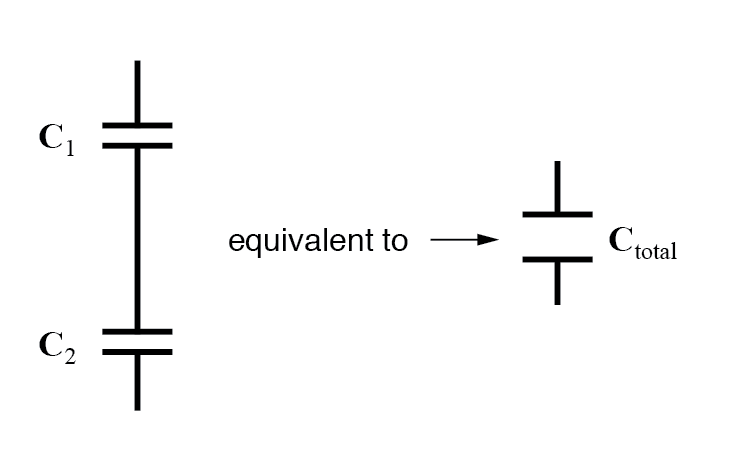
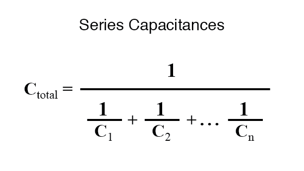
Thus, the total capacitance is less than any one of the individual capacitors’ capacitances. The formula for calculating the series total capacitance is the same form as for calculating parallel resistances:
Capacitors in parallel
When capacitors are connected in parallel, the total capacitance is the sum of the individual capacitors’ capacitances. If two or more capacitors are connected in parallel, the overall effect is that of a single equivalent capacitor having the sum total of the plate areas of the individual capacitors. As we’ve just seen, an increase in plate area, with all other factors unchanged, results in increased capacitance.
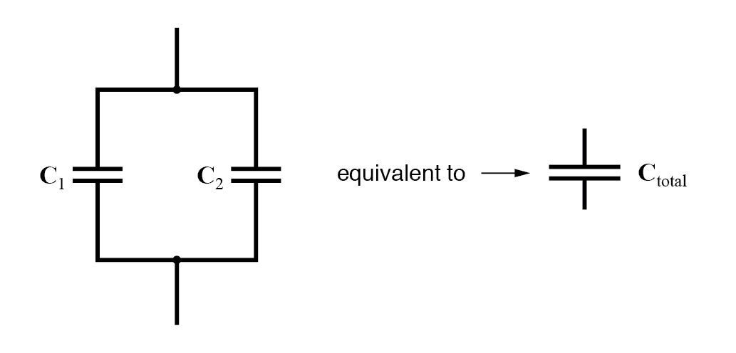
Thus, the total capacitance is more than any one of the individual capacitors’ capacitances. The formula for calculating the parallel total capacitance is the same form as for calculating series resistances:
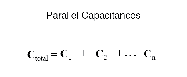
As you will no doubt notice, this is exactly the opposite of the phenomenon exhibited by resistors. With resistors, series connections result in additive values while parallel connections result in diminished values. With capacitors, its the reverse: parallel connections result in additive values while series connections result in diminished values.