4. Technical Basics 6 - Transformers - Temperature
4.28 Transformers
- Understand the concept of mutual inductance.
- Understand and apply the formulae relating transformer primary and secondary turns to primary and secondary potential differences and currents.
Mutual inductance
In its simplest form a transformer consists of two windings or coils (inductors ) wound on a common core so that their magnetic fields can interact. The core or former could be some kind of insulating material that is non-magnetic such as a cardboard or plastic tube. The coils could be wound side by side or one on top of the other provided they are electrically insulated from each other. The diagram below shows the circuit symbol for a very simple transformer.
If an alternating voltage is applied to coil one, its magnetic field will also alternate at the frequency of the applied voltage. Because coil one is in close proximity to coil two, the magnetic field from coil one will cut the wires of coil two, inducing a current into the second coil. This is known as mutual induction. We call coil one in this case the primary and coil two the secondary.
Mutual inductance (more detail optional)
Mutual Inductance is the basic operating principal of the transformer, motors, generators and any other electrical component that interacts with another magnetic field. Then we can define mutual induction as the current flowing in one coil that induces a voltage in an adjacent coil.
But mutual inductance can also be a bad thing as “stray” or “leakage” inductance from a coil can interfere with the operation of another adjacent component by means of electromagnetic induction, so some form of electrical screening to a ground potential may be required.
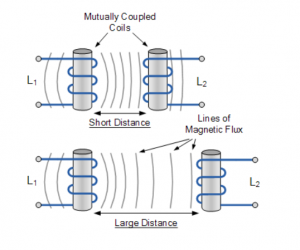
The amount of mutual inductance that links one coil to another depends very much on the relative positioning of the two coils. If one coil is positioned next to the other coil so that their physical distance apart is small, then nearly all of the magnetic flux generated by the first coil will interact with the coil turns of the second coil inducing a relatively large emf and therefore producing a large mutual inductance value.
Likewise, if the two coils are farther apart from each other or at different angles, the amount of induced magnetic flux from the first coil into the second will be weaker producing a much smaller induced emf and therefore a much smaller mutual inductance value. So the effect of mutual inductance is very much dependant upon the relative positions or spacing, ( S ) of the two coils and this is demonstrated below.
Mutual Inductance between Coils

The mutual inductance that exists between the two coils can be greatly increased by positioning them on a common soft iron core or by increasing the number of turns of either coil as would be found in a transformer.
If the two coils are tightly wound one on top of the other over a common soft iron core unity coupling is said to exist between them as any losses due to the leakage of flux will be extremely small. Then assuming a perfect flux linkage between the two coils the mutual inductance that exists between them can be given as.

- Where:
- µo is the permeability of free space (4.π.10-7)
- µr is the relative permeability of the soft iron core
- N is in the number of coil turns
- A is in the cross-sectional area in m2
- ℓ is the coils length in meters
Mutual Induction

Here the current flowing in coil one, L1 sets up a magnetic field around itself with some of these magnetic field lines passing through coil two, L2 giving us mutual inductance. Coil one has a current of I1 and N1 turns while, coil two has N2 turns. Therefore, the mutual inductance, M12 of coil two that exists with respect to coil one depends on their position with respect to each other and is given as:

Likewise, the flux linking coil one, L1 when a current flows around coil two, L2 is exactly the same as the flux linking coil two when the same current flows around coil one above, then the mutual inductance of coil one with respect of coil two is defined as M21. This mutual inductance is true irrespective of the size, number of turns, relative position or orientation of the two coils. Because of this, we can write the mutual inductance between the two coils as: M12 = M21 = M.
Then we can see that self inductance characterises an inductor as a single circuit element, while mutual inductance signifies some form of magnetic coupling between two inductors or coils, depending on their distance and arrangement, an hopefully we remember from our tutorials on Electromagnets that the self inductance of each individual coil is given as:
 and
and
By cross-multiplying the two equations above, the mutual inductance, M that exists between the two coils can be expressed in terms of the self inductance of each coil.
![]()
giving us a final and more common expression for the mutual inductance between the two coils of:
Mutual Inductance Between Coils
However, the above equation assumes zero flux leakage and 100% magnetic coupling between the two coils, L1 and L2. In reality there will always be some loss due to leakage and position, so the magnetic coupling between the two coils can never reach or exceed 100%, but can become very close to this value in some special inductive coils.
If some of the total magnetic flux links with the two coils, this amount of flux linkage can be defined as a fraction of the total possible flux linkage between the coils. This fractional value is called the coefficient of coupling and is given the letter k.
Coupling Coefficient
Generally, the amount of inductive coupling that exists between the two coils is expressed as a fractional number between 0 and 1 instead of a percentage (%) value, where 0 indicates zero or no inductive coupling, and 1 indicating full or maximum inductive coupling.
In other words, if k = 1 the two coils are perfectly coupled, if k > 0.5 the two coils are said to be tightly coupled and if k < 0.5 the two coils are said to be loosely coupled. Then the equation above which assumes a perfect coupling can be modified to take into account this coefficient of coupling, k and is given as:
Coupling Factor Between Coils
 or
or
When the coefficient of coupling, k is equal to 1, (unity) such that all the lines of flux of one coil cuts all of the turns of the second coil, that is the two coils are tightly coupled together, the resulting mutual inductance will be equal to the geometric mean of the two individual inductances of the coils.
Also when the inductances of the two coils are the same and equal, L1 is equal to L2, the mutual inductance that exists between the two coils will equal the value of one single coil as the square root of two equal values is the same as one single value as shown.
![]()
Mutual Inductance Example No1
Two inductors whose self-inductances are given as 75mH and 55mH respectively, are positioned next to each other on a common magnetic core so that 75% of the lines of flux from the first coil are cutting the second coil. Calculate the total mutual inductance that exists between the two coils.

Mutual Inductance Example No2
When two coils having inductances of 5H and 4H respectively were wound uniformly onto a non-magnetic core, it was found that their mutual inductance was 1.5H. Calculate the coupling coefficient that exists between.

In the next tutorial about Inductors, we look at connecting together Inductors in Series and the affect this combination has on the circuits mutual inductance, total inductance and their induced voltages.
Turns ratio
Use of Transformers
If we constructed a transformer with 100 turns on its primary and 10 turns on its secondary we would have a turns ratio of 100 to 10 or 10:1. The magnetic field from the hundred turns (primary) will only cut ten turns (secondary) and so the induced voltage (secondary) will not be the same as the applied voltage (primary).
If an alternating voltage of 100 V RMS is applied to the primary, we would have an induced voltage of 10 V RMS in the secondary. This would be a step down transformer as we have stepped the primary voltage of 100 V RMS down to 10 V RMS.
If we now applied 10 V RMS to the ten turn winding, making it the primary, we would induce a voltage of 100 V RMS in the secondary making it a step up transformer. Transformers therefore find most use in translating voltage levels. This also enables them to act as impedance matching devices.
Turns Ratio and Voltage
The turns ratio of a transformer is also the voltage ratio that will occur between voltage applied to the primary and voltage available at the secondary. In the above example the turns ratio is 10:1 ie ten times as many turns on the primary as there are on the secondary. The ratio of voltages is the same as the turns ratio of the transformer.
It is common practice to refer to the number of turns on the primary as Np and on the secondary as Ns. Similarly the primary voltage is Ep and the secondary voltage is Es. We can express the relationship between turns ratio and voltage ratio as,
Np/NS = Ep/ES
Example
If we had a transformer with a turns ratio of 20:1, primary to secondary, and applied 400 V RMS to the primary what voltage would be induced in the secondary?
We are told that our turns ration is 20:1 and that 400 V is applied to the primary so our formula becomes
20/1 = 400/Es
Re-arranging the formula to find Es gives us,
Es = 400/20 = 20
The voltage induced in the secondary will be 20 V.
Notice that it is not necessary to know precisely how many turns there are on the transformer. It is the turns ratio that determines what voltage will appear at the secondary. If we applied 40 V RMS to the primary of our 20:1 transformer we would have 2 V RMS induced in the secondary.
Power
So far we have looked at turns ratio and its effect on voltage. If we multiply current and voltage we get power.
P = V * I
Taking our ten to one transformer as an example again we said that the voltage applied to the primary was 100 V RMS. If the primary current was one amp then the power consumed by the primary of our transformer is
P = 100 * 1 = 100 Watts.
Now on our secondary we measured 10 Volts RMS but the power in the secondary will remain the same as that in the primary. We are therefore able to draw ten amps from the secondary, so the power that our secondary can supply is
P = 10 * 10 = 100 Watts.
So there would appear to be no loss in power between the primary and the secondary, and this is true for a theoretical transformer that has no losses. However as you might guess nothing in nature is one hundred percent efficient, and transformers do have losses that limit their practical efficiency. However with careful choice of the core material and attention to the thickness of the copper wire in the windings transformers can achieve efficiencies in the high ninety per cent range.
Turns Ratio and Current
Taking our 10:1 transformer as an example, if the current flowing in the primary is 1 Amp we will be able to draw 10 amps from the secondary because we have stepped the voltage down.
If we reverse the transformer (1:10) so our supply is connected to the 10 turns side and supply 10 amps then only one amp will be able to be drawn from the secondary (100 turns) because we have stepped the voltage up.
So not only do transformers allow us to change voltages they also allow us to change the current we can draw from them. Again we need not concern ourselves with the number of turns on the primary and secondary. It is the turns ratio that determines what current can be drawn from the transformer. The current ratio for any transformer is the inverse of the turns ratio.
Np/NS = Is/Ip
Example
A transformer with a turns ratio of 40:1, primary to secondary has one amp flowing through its primary winding. What current can be drawn from the secondary?
Applying our formula
Np/Ns = Is/Ip
And re-arranging to find Is we have
Is = Np/NS * Ip
Is = 40/1 x 1 = 40 amps
We will be able to draw 40 amps from our secondary winding.
4.29
- Understand and apply the formula relating transformer primary and secondary turns to primary and secondary impedances.
Impedance Matching
We have previously seen that impedance is a relationship, or ratio, between voltage and current (Z=V/I). If a voltage is fed to a conductor (which has a resistance) a certain current will result, however if a device with a different resistance or impedance is placed at the end of the conductor the same voltage will cause a different current relationship. This mismatch creates a loss of power through reflected voltage and standing waves (which will be discussed later) so in many cases it is important to change the voltage/current ratio at the end of the conductor to match it to the device.
If for example we have a stereo amplifier which is designed to feed 8Ω speakers, the impedance of the speakers match the output of the amplifier (Z=V/R). If this amplifier is connected to speakers with a different impedance it would probably damage the speakers and possibly the amplifier. At the best a distorted sound would result.
Because a transformer changes the current /voltage ratio it can be used to match impedances.
The impedance ratio of a transformer is related to the turns ratio and is expressed as
Np/Ns = √(Zp/Zs)
Where Np is the number of primary turns; Ns is the secondary turns; Zp is the impedance looking into the primary from the power source; and Zs is the impedance of the load on the secondary.
Example:
What turns ratio is required on a transformer to match a source with a 600Ω impedance to a load of 50Ω impedance?
Np/Ns = √(Zp/Zs)
= √(600/50)
= √12
= 3∙464
Np/Ns = 3.464/1 or a ratio Np : Ns = 3∙464 : 1
So 3∙646 turns on the primary for every 1 turn on the secondary.
4.30
- Understand the cause and effects of eddy currents and the need for laminations (or ferrites) in transformers.
- Understand the meaning of the terms copper, hysteresis and external induction loss.
Transformer losses
We have said that we can improve the mutual coupling between the windings of a transformer by adding an iron core. However iron is also an electrical conductor and it will have currents induced in it by the changing magnetic field of the primary winding in the same manner as the secondary. The core though, only represents one turn, but while the voltage induced in it will be low, the current can be quite high.
As the current in the primary reverses direction the current induced in the core tries to continue in its original direction opposing the change in direction of the primary current. Eventually the primary current reaches a sufficient level to cause the current in the core to change direction also. So we have a circulating current in the core that is always trying to oppose the change in the primary current. This process consumes some of the power supplied to the transformer, which means that less than our theoretical one hundred percent of power is available to our secondary.
The currents circulating in the core are known as Eddy currents are responsible for causing the core to heat up. If you have ever placed your hand on the core of an operating transformer you will find that it is warm. The heat represents the power lost due to the Eddy currents.
To reduce Eddy current losses the cores of transformers are made of many individual laminations that are insulated from each other with a suitable varnish. Packed close together they still act as an effective magnetic core. However the level of Eddy currents induced in them is greatly reduced since electrically they now represent lots of resistances connected in series. Therefore the Eddy currents will be lower in magnitude than for a solid core.
As well as inducing a current into the core the changing magnetic field is causing the core to become magnetised. To do this the magnetic domains in the core line up in one direction. When the current in the primary windings changes direction so the magnetic field surrounding changes thus causing the magnetic domains in the core to change direction. This is a physical change, albeit at an almost atomic level, in the core material which uses energy from the primary. The magnetic field change causes heat in the core and is a loss known as hysteresis loss.
As frequency is increased the domains do not have time to line up fully before the reversing current causes the opposite magnetic field which forces the domain movement to stop and reverse. At a low frequency the line up of the domains may be complete, or almost complete, before the current reversal occurs whereas at a higher frequency more energy is required to stop the domain movement and restart it in the opposite direction. Hysteresis losses therefore tend to increase with frequency.
The other main source of loss is the resistance of the copper wire used for the windings. In a transformer that has several hundred or thousands of turns the resistance of the wire cannot be ignored. It places an upper limit on the current that can be drawn from the transformer. Again, any losses due to the resistance of the windings produce heat.
The fourth loss in a transformer is not actually caused within the transformer. The expanding magnetic field may intersect with conductors that are outside the transformer and will therefore induce currents into these external conductors which may or may not be other circuits. The energy lost in producing these current is an effective loss for the transformer and are known as external induction losses. In well designed transformers and surrounding circuits these losses may be very small but it can become very important in circuit design as induced currents in other circuits will create noise. To stop external induction, transformers in close proximity to other circuits are often shielded by a surrounding cover which is earthed.
4.31 Filters
- Identify the circuits and related response curves of low pass, high pass, band pass and band stop (notch) filters. Understand the concepts of cut-off frequency and insertion loss.
- Recall that crystals, ceramics, and resonant cavities can be used in filter circuits.
Filters
Filters are generally designated by their function and are classified as low pass, high pass, band pass or band stop. Generally filters consist of inductors and capacitors in a circuit and use the reactance values of the components to permit frequencies to pass through them or short them to ground.
It is important to note that the definition of a filter (high or low pass) depends upon the frequencies that are passed in relation to the cutoff point. One filter (Low pass) may pass all frequencies below 3MHz while another (high pass) passes all frequencies above 1kHz. The filter that passes all frequencies below 3MHz is still a low pass filter even though the frequencies it passes are well above the cutoff point of the high pass filter at 1kHz. It is the frequency that is passed in relation to that filters cutoff that determines high or low pass.
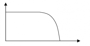
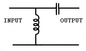
Low Pass Filter
A low pass filter is designed to pass frequencies below a certain value and block frequencies above that value.
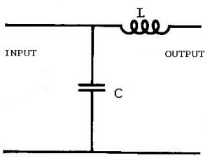
In this configuration the inductor’s reactance increases with a rise in frequency while the capacitor’s decreases. At low frequencies the reactance of the capacitor is larger than that of the inductor and so low frequencies, seeking the path of least resistance, flow through the inductor to the output. Depending on the values of the inductor and capacitor at some frequency the reactance of the inductor will become larger than the capacitor and signals above that frequency will again follow the path of least resistance and bypass the output returning straight to the ground line.
The response curve for the filter above would be fairly low Q.
Amplitude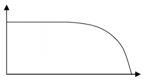
Frequency
Low Pass Low Q
More capacitors and inductors can be added to the circuit to enhance the filter’s characteristics.
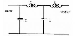
Amplitude
Frequency
Low Pass High Q
Low pass filters can be used at the output of a transmitter to prevent radiation of harmonic frequencies.
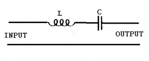
High Pass Filter
A high pass filter is designed to pass high frequencies and bypass low frequencies away from the output. Again the frequency point at which the filter becomes effective depends upon the components values.
In this the high frequencies will have less reactance at the capacitor and the low frequencies will have less reactance through the inductor.
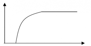
High pass filters can be used in receive antennas to prevent pickup of lower frequency interfering signals.
Band Pass Filters
As the name suggests this filter is designed to pass a range or band of frequencies.
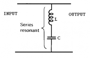
This can be accomplished with a series resonant circuit in series. This has a low impedance at resonance and therefore a high current flow. Thus passing the resonant frequency and blocking other frequencies.
It could also be done by inserting a parallel resonant circuit in shunt (or across) the circuit
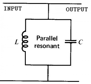
This creates a bypass circuit with a high impedance at resonance and therefore forces the resonant frequency to the output while bypassing other frequencies.
Most bandpass filters are a combination of series and parallel circuits.
The response curve for a Band Pass filter is shown below
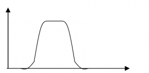
Band pass filters are commonly used between receiver stages to ensure a clear noise free output.
Band Stop Filter or Notch filter
A band stop filter must stop a band or range of frequencies. This is the opposite to a band pass filter and can be done with the same circuits placed in reversed positions.
A series resonant circuit in shunt.
This provides a bypass circuit with low impedance at the resonant frequency so only frequencies off resonance will be passed to the output. The resonant frequencies will be shunted away from the output.
A parallel resonant circuit placed in series with the output.
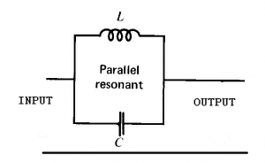
This places a high impedance at resonance in the circuit blocking that band of frequencies.
The response curve of a Band Stop filter is shown below
Amplitude
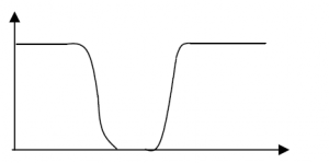
Frequency
Band Stop
If the Band stop filter is given a higher Q it is known as a notch filter
Band Stop filters also known as notch filters can be used to block a narrow band of frequencies in receivers.
To understand the principles of band pass and band stop the impedance and resulting current flow must be thoroughly understood.
Cut Off
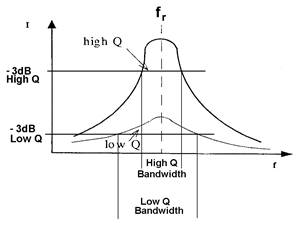
It is important to recognize where a filter is considered to have significant attenuation, that is to say where on its response curve the signal is diminished enough to ignore. On power curves this is accepted to be at −3dB or where the incoming signal is reduced to half power and for this reason they are also known as half power points. Beyond this point the signal diminishes rapidly.
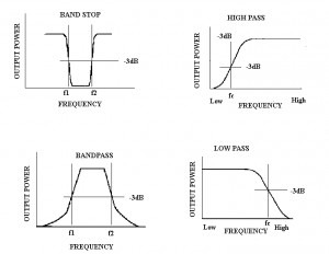
Curves showing -3dB (half-power) points.
It is also important to realise that the half power points combine with the Q of a circuit to determine its bandwidth.
Normally a curve would be drawn showing the actual frequencies on the horizontal axis and the dB points on the vertical axis
Insertion Loss
Any component or circuit will have losses of some degree. The loss in the signal created by a filter is known as insertion loss and is often shown on the filter curve diagrams.
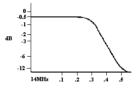
A low pass filter curve for the amateur 14MHz band.
Crystal and cavity filters
Cavity Filters
Cavity filters are generally used at repeater sites where a receiver and a transmitter are in very close proximity. Considering that the transmitter is radiating while the receiver is receiving and the two antennas are generally mounted on the same mast (if not the same antenna) the filtering system must be able to reject high power signals that are only a few hundred kilohertz off the resonant frequency.
Cavity filters are actually two carefully designed resonant circuits.
A series tuned circuit as a band pass and a parallel tuned circuit as a band stop or notch filter. A very high Q must obtained due to the closeness of the transmit and receive frequencies (on VHF 600kHz is the normal split). To obtain the components with high capacitive and inductance values compared to the resistive values cavity filters are physically large. Due to the very accurate frequency response required they are also expensive.
To enhance the performance cavities are usually used in pairs or triples with both transmit and receive lines being filtered.
Crystal Filters
A crystal, because of its resonant frequency properties can be used as either a series resonant or parallel resonant circuit and therefore used in filters. A crystal filter has a very high Q but low power handling capabilities.
Ferrite Beads and Toroids
Ferrite beads and toroids increase inductance in a line thereby blocking unwanted RF currents that can otherwise generate interference.
4.32 Screening
- Recall that screening with thin metal sheet is effective in reducing unwanted radiation from equipment and between stages within equipment.
Screening
Screening with thin metal sheet is effective in reducing unwanted radiation from equipment and between stages within equipment.
4.33 Temperature effects
- Recall that temperature has an effect on the value of components. Components with a negative coefficient will reduce in value as temperature rises whereas those with positive coefficient will increase in value. Understand how a components temperature coefficient impacts on the design of a tuned circuit.
Temperature Co-efficient
All components have a response to a change in temperature. This may be the ambient temperature (temperature of the substance surrounding the component) or a change in the components temperature. Ambient temperature can be as simple as the air temperature on a summers day compared to the air temperature on a winters day or can be affected by where the component is located. Within a box that contains other components for example, the ambient temperature will be higher than the surrounding room, particularly if the other components operate at temperature such as valves.
A component is said to have a positive temperature co-efficient if it increases its value with a rise in temperature (in a resistor the resistance increases with a rise in temperature) and a negative co-efficient if the value decreases with an increase in temperature.
Temperature co-efficient is not confined to resistors but affects many components and must be allowed for in circuit design.
If for example a 40W resistor is used in a circuit where it must dissipate 40W of power then the heat generated will cause the resistance to alter and the resistor will not operate at its stated value.
Drift and Stability
Drift is the slow unwanted change in frequency of an oscillator. One of the main causes of drift in L-C oscillators is unwanted capacitance changes, usually due to temperature changes. If the capacitance is high in relation to the inductance then the capacitance changes will have a smaller percentage change on the overall frequency.
Crystals also may change their frequency with temperature although it is not as pronounced.
To ensure good stability of an L-C oscillator it should have
- a) a high C to L ratio;
- b) a well regulated power supply
- c) good isolation between the oscillator and load
- d) components with low temperature co-efficient
- e) not be exposed to large temperature changes
- f) have all components rigidly mounted