4. Technical Basics 4 - AC circuits / Phase and Impedance
4.16 AC circuits
- Understand that the root mean square (RMS) value of a sine wave has the same heating effect as a direct current of the same value and that it is equal to 0.707 of it’s peak value.
Sine Wave Values
To work with Sine waves there are several definitions which must be understood:
Amplitude means largeness, width or breadth. In our context it refers to the variation of the wave from zero. It can be measured as either a Peak Value or Peak‑to‑Peak value.
The Peak value is the maximum value the wave attains. In the first example above it is 1V. The phase (+ or – ) does not matter – the Max value is 1 volt
The Peak to Peak value is the variation between max in one direction and max in the other. In the top example it is 2V. +1V to –1V = 2V.
Average Value is the average of the wave. The average value of a Sine wave is 0×637 of its peak value.
RMS Value The RMS (Root Mean Square) value is 0×707 of its peak value. The RMS value is the value specified for all house wiring in Australia. Its value is 230 Volts RMS.
The RMS value of a sine wave is that value that produces an equivalent heating effect in a resistive load as the same voltage from a DC source.
So a 230 Volt RMS source supplying a resistive load of one hundred ohms will produce a current of
I = V/R
= 230/100
= 2·3 Amps
The power dissipated in the resistor will be
P = I2R
= 2·3 * 2·3 * 100
= 529 Watts
If we connected a 230 Volt DC source to our 100 ohm resistor and used the same formulas we would have,
I = 2.3 Amps
P= 529 Watts.
When specifying or reading the value of an AC source it is essential that you know what value you are reading. Is it the Peak value, the Peak to Peak value, the Average value or the RMS value. This may seem confusing but if you remember the relationships for each value of an AC source you can calculate the value you are interested in if given any one of the other values.
Example.
We know that our household wiring is 230 Volts RMS. What are the Peak, Peak to Peak and Average values?
Peak Value
V Peak = 1·414 * RMS
= 1·414 * 230
= 325.22 Volts
Peak to Peak Value
V Peak to Peak = 2 * V Peak
= 2 * 325.22
= 650.44 Volts
Or working from our RMS value
V Peak to Peak = 2·828 * RMS
= 2·828 * 230
= 650.44 Volts
Average Value
V Average = 0·637 * V Peak
= 0·637 * 325.22
= 207·17 Volts
4.17
- Recall that the period (time) of a sine wave is equal to 1/f seconds and that the frequency of a sine wave is equal to 1/T (where f = frequency in Hertz and T = time in seconds).
Frequency and Period
One complete revolution of a rotating conductor in a magnetic field produces one cycle. A cycle is the amount of time from a point on a sine wave to a point on the next wave of the same amplitude and polarity.
The frequency of a sine wave is the number of cycles per second measured in Hertz (Hz). The time it takes to complete one cycle is known as the period of the waveform. Our household power has a frequency of 50 Hz. Fifty complete cycles occur in one second.
The time taken for just one cycle is the period of the waveform and is calculated from the following formula
Period (in seconds) = 1 / Frequency in Hertz
T = 1/f
Example
What is the period of an AC waveform that has a frequency of 50 Hz
T = 1 /50
= 0·02 Second
= 20 mS
The wavelength of a sine wave is the distance travelled by the leading point of one cycle. Since a sine wave propagates at the speed of light, 300,000,000 meters per second, if its frequency is known the wavelength can be calculated from the following formula. The symbol for wavelength is l (lambda).
The relationship with frequency is,
l (in meters) = 300,000,000 ¸ f (in Hertz) or f (in Hertz) = 300,000,000 ¸ l (in meters)
It is often easier to use:
l (m) = 300 ¸ f (MHz) or f (MHz) = 300 ¸ l (m)
4.18
- Understand that AC waveforms are expressed in degrees and that a complete cycle is equal to 360 degrees.
Sine wave period

To create the sine wave curve pictured below, consider the illustration above. Imagine the hypotenuse, C, of the triangle sweeping around the circle in a counter-clockwise rotation. At each point along the sweep, you get back the length of A on the Y axis. The circle is 1 unit in radius, so the value goes from 0 to 1, then back to 0, then 0 to -1 and back to 0 again.The reason you get the "sine wave" curve below is that you are progressing through the values of the 'sweep' over time.
The sin() function uses as its input the angle, ![]() , of the counter-clockwise 'sweep', in radians, not degrees.
, of the counter-clockwise 'sweep', in radians, not degrees.
There are 2* PI radians in 360 degrees.
radians = degrees * (PI / 180)
degrees = radians * (180 / PI)

4.19 Phase and impedance
- Recall that for a resistor, the PD and current are in phase.
- Recall that current lags potential difference by 90 degrees in an inductor and that current leads by 90 degrees in a capacitor.
- Recall that the term ‘reactance’ describes the opposition to current flow in a purely inductive or capacitive circuit where the phase difference between E and I is 90 degrees.
- Understand and apply the equations for inductive and capacitive reactance. Understand the application of the formulae XL=2πFL and XC= 1/2πFC
Phase shift
Generally, AC circuits may contain Resistors, Inductors and (or) Capacitors. Impedance, represented by the letter "Z" and measured in Ohms, is the total opposition that a circuit offers to the flow of AC Current, it is a combination of Resistance R and Reactance X, Z = R + jX, Figure 1.

Figure 1: Impedance Diagram
In AC circuits, because the existence of Reactive Components, the Voltage and Current may not reach the same amplitude peaks at the same time, they generally have a difference in timing. This timing difference is called Phase Shift, f, 0° ≤ f ≤ 90°, and is measured in angular degrees.
A circuit that contains only Resistors is called Resistive Circuit. There is no Phase Shift between the Voltage and the Current in a Resistive Circuit, Φ = 0°, Figure 2a. The Current is "In-Phase" with the Voltage.

Figure 2a: V-I Relationship of the Circuit R
Capacitors and Inductors are called Reactive Components, in which the Voltage and Current are "Out-of-Phase" with each other. In an Inductor, the Voltage leads the Current by 90°, Φ = 90°, Figure 2b; in a Capacitor, the Voltage lags the Current by 90°, Φ = -90°, Figure 2c.

Figure 2b: V-I Relationship of Circuit L

Figure 2c: V-I Relationship of Circuit C
A circuit that contains Inductors and (or) Capacitors is called Reactive Circuit, which can be classified into Inductive Circuit, XL > XC, and Capacitive Circuit, XC > XL.
Figure 3a shows an Inductive Circuit that consists of R and L in series. As the Inductor opposes a change in Current and stores energy from the Power Supply in the form of a Magnetic Field, the Inductor Voltage vL leads the Inductor Current iL by 90° and leads the Power Supply Voltage v by a Phase Angle Φ.
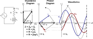
Figure 3a: V-I Relationship of the Circuit RL
Figure 3b shows a Capacitive Circuit that consists of R and C in series. As the Capacitor opposes a change in Voltage and stores energy from the Power Supply in the form of an Electric Field, the Capacitor Voltage vC lags the Capacitor Current iC by 90° and lags the Power Supply Voltage v by a Phase Angle Φ.
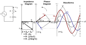
Figure 3b: V-I Relationship of the Circuits RC
Reactance
Capacitive Reactance
In an AC circuit a capacitor is continually charging and discharging and its opposition to the change is called capacitive reactance (XC). It is similar to resistance and is measured in Ohms.
Unlike resistance no power is dissipated by reactance. The energy is ‘borrowed’ during one part of the cycle and ‘paid back’ during the next part. Because capacitors do not charge instantly the amount of charge and therefore its opposition or reactance is affected by frequency.
The formula for calculating the reactance of a capacitor is:
XC = 1/2πfC
Where XC is the reactance in W (Ohms);
f is the frequency in Hz (Hertz); &
C in capacitance in F (Farads).
As XC is inversely related to frequency the reactance will decrease when frequency increases.
Imagine a light globe connected in series with a capacitor and an EMF. If the EMF is DC the globe will light very briefly as the capacitor charges, dimming down as the current flow reduces and will go out when the cap is charged as there is no current flow.
If the EMF is AC with a low frequency the globe will light and dim as the capacitor charges/discharges and the current flow changes. As the frequency is increased the globe will get brighter as the capacitor does not fully charge/discharge and the current flow is greater.
Example 1:
What is the reactance of a 20nF capacitor operating in a circuit with a frequency of 6kHz.
XC = 1/2ΠfC
= 1 / 6∙283*6E3*20E-9
= 1 / 753∙96E-6
= 1326∙33Ω
Example 2:
If we double the operating frequency. A 20nF capacitor operating at 12kHz
XC = 1 / 6∙283*12E3*20E-9
= 1 / 1507∙92E-6
= 663∙16Ω
Inductive Reactance
According to Faraday’s law of Induced Voltage the voltage depends on the strength of the magnetic flux, the number of turns in the coil and the speed of the relative movement.
In an AC circuit the magnetic field surrounding the inductor is continually building and collapsing in time with the current flow. The field from each turn of the coil will cut the adjacent turns inducing an opposing current. This is known as a ‘back EMF’.
Because the value of the induced voltage depends on the speed of the relative movement between the magnetic field and the conductor, the value of the back EMF will depend on the AC frequency. The higher the frequency the more direction changes per second and therefore the faster the rate of change or speed of relative movement.
Inductive reactance increases with frequency
The opposition is called inductive reactance (XL). It is similar to resistance and is measured in Ohms.
Remember, unlike resistance no power is dissipated by reactance.
The formula for calculating reactance of an inductor is:
XL = 2πfL
Where Xl is the reactance in W (Ohms);
f is the frequency in Hz (Hertz); &
L is the inductance in H (Henry’s).
Example:
If an inductance of 50mH is supplied by an AC source with a frequency of 50Hz, what is its XL.
XL = 2πfL
= 2*3∙141*50*50E-3
= 15.7Ω
4.20
- Understand that impedance is a combination of resistance and reactance and apply the formulae for impedance and current in a series CR or LR circuit.
Impedance
Impedance and reactance
An element in a DC circuit can be described using only its resistance. The resistance of a capacitor in a DC circuit is regarded as an open connection (infinite resistance), while the resistance of an inductor in a DC circuit is regarded as a short connection (zero resistance). In other words, using capacitors or inductors in an ideal DC circuit would be a waste of components. Yet, they are still used in real circuits and the reason is that they never operate with ideally constant voltages and currents.
As opposed to constant voltage circuits, in AC circuits the impedance of an element is a measure of how much the element opposes current flow when an AC voltage is applied across it. It is basically a voltage to current ratio, expressed in the frequency domain. Impedance is a complex number, which consists of a real and an imaginary part:
![]()
where Z is the complex impedance. The real part R represents resistance, while the imaginary part X represents reactance. Resistance is always positive, while reactance can be either positive or negative. Resistance in a circuit dissipates power as heat, while reactance stores energy in the form of an electric or magnetic field.
Impedance of a resistor
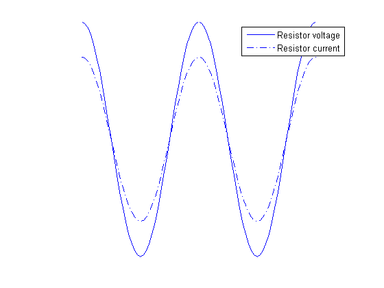
Resistors in AC circuits behave the same way they do in DC circuits. Basically, the impedance of a resistor consists only of the real part, which is equal to the resistance of the resistor. Therefore, the impedance of a resistor can be expressed as:
![]()
where Z is the impedance, and R is the resistance of the resistor. It is obvious that a resistor has no reactance, and can therefore store no energy. Also, when a voltage is applied across the resistor, the current flowing through the resistor will be in phase with the voltage, as can be seen in this illustration:
Impedance of a capacitor
Capacitors are components which introduce a certain capacitance into a circuit. They are used to temporarily store electrical energy in the form of an electric field. While this definition is technically correct, it doesn’t mean much to a hobbyist or even to most engineers. It is perhaps more appropriate to say that capacitors are used to lag the voltage by 90 degrees compared to the current, in the time domain. This effect is better described graphically:
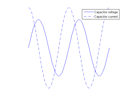
As can be seen from the graph, the voltage of a capacitor lags behind the capacitor current. Alternatively, it can be said that the capacitor current leads capacitor voltage by 90 degrees. In order to represent this fact using complex numbers, the following equation is used for the capacitor impedance:
![]()
where ZC is the impedance of a capacitor, ω is the angular frequency (given by ω=2πf, where f is the frequency of the signal), and C is the capacitance of the capacitor. Several facts are obvious from this formula alone:
- The resistance of an ideal capacitor is zero.
- The reactance of an ideal capacitor, and therefore its impedance, is negative for all frequency and capacitance values.
- The effective impedance (absolute value) of a capacitor is dependent on the frequency, and for ideal capacitors always decreases with frequency.
Impedance of an inductor
Similarly, inductors are components which introduce a certain inductance into a circuit. They are used to temporarily store electrical energy in the form of a magnetic field. Therefore, inductors are used to lag the current by 90 degrees compared to the voltage, in the time domain. The following graph explains this phenomenon:
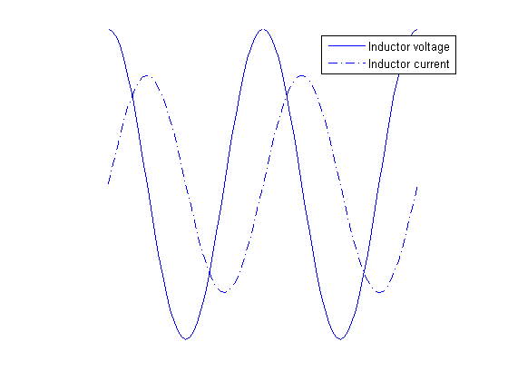
The voltage of an inductor leads the capacitor current by 90 degrees. The following equation is used for the impedance of an inductor:
![]()
where ZL is the impedance of the given inductor, ω is the angular frequency, and L is the inductance of the inductor. Again, several conclusions can be drawn from this formula:
- The resistance of an ideal inductor is zero.
- The reactance of an ideal inductor, and therefore its impedance, is positive for all frequency and inductance values.
- The effective impedance (absolute value) of an inductor is dependent of the frequency and for ideal inductors always increases with frequency.
Ohm’s law
Ohm’s law was originally formulated for DC circuits, and it states:
![]()
To make sense for AC circuits, it was later expanded with the use of complex numbers, and the new formulation is:
![]()
where U is the complex voltage between two points, I is the complex current, and Z is the complex impedance. Since impedance is always regarded as a complex number, we have omitted the underscore for the impedance throughout this text.
The notion of complex voltages and currents can be confusing at first, so let’s try to explain this first. AC circuits are often in a steady state, where there are one or more power sources operating at the same frequency, giving a sinusoidal output. In this case, it can be proven that all the voltages and currents in the circuits are also sinusoidal waveforms oscillating, all of them oscillating at the same angular frequency, ω. However, these voltages and currents are not in phase, generally speaking. If the voltage in an AC circuit is given as a cosine wave such as this one:
![]()
where u(t) is the voltage between some two points in a circuit given as a function of time, UM is the amplitude, ω is the angular frequency, and ΦU is the phase, then the complex representation of this voltage is:
![]()
On a circuit-wide scale, it is common to use one signal as the phase-reference signal. This means that it is assumed that the phase of that signal is zero, and phases of all other signals (voltages and currents) are determined in regard to that reference.
Equivalent impedances
Connection in series
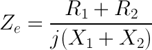
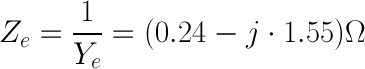
If two impedances are connected in series, the equivalent impedance is obtained by simple addition - Ze=Z1+Z2. The addition of two complex is easily perfomed like this:
![]()
![]()
For example, a 10 Ω resistor connected in series with a 1mF capacitor at 100Hz will have the equivalent impedance of:
![]()
The effective impedance, also called the magnitude of the impedance is calculated as:
![]()
In our example, the magnitude of the impedance equals:
![]()
Connection in parallel
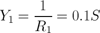
To obtain the equivalent impedance of two impedances connected in parallel, we will first define admittance. The unit of admittance is a siemens [1 S] and it is the measure of how easily an element will allow current to flow, and its value is the inverse of impedance:

The equivalent admittance of two impedances connected in parallel is equal to the sum of individual admittances:
![]()
If we use the same values as in the previous example, we can easily obtain:
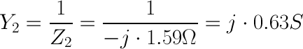
![]()
This gives the impedance magnitude of:
![]()
Impedance of LRC circuit (optional)
Calculating Impedance
In AC circuits, Ohm's Law takes the more general form: E = I⋅Z, where E is voltage and I is current, as before. The new term, Z, is impedance, a vector combination of:
- Resistance, R (in ohms), with voltage drops in phase with the current.
- Inductive reactance, XL (in ohms), with voltage drops leading the current by 90°.
- Capacitive reactance, XC (in ohms) with voltage drops lagging the current by 90°.
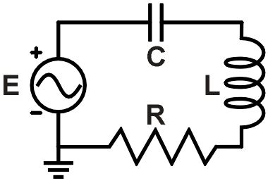 f = 6.4 kHz R = 120 Ω L = 3.6 mH C = 0.38 μf |
|
Figure 1. Example RLC circuit |
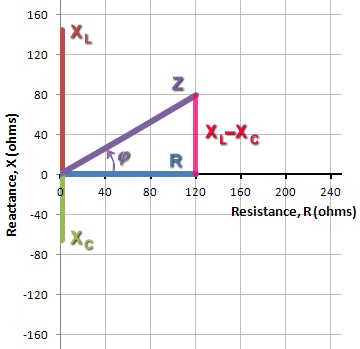 |
| Figure 2. Vector sum of R and XL−XC yields Z |
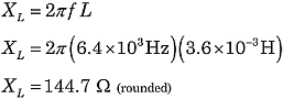
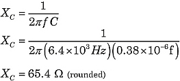
From the formulas for XL and XC, you can see that reactances depend on both the component values L and C, as well as the AC frequency, f:
![]() and
and 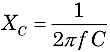
where f is the frequency in Hertz (or sec−1), L is inductance in Henries, and C is capacitance in farads. Because XL and XC are 180° different in phase, the total reactance X of a series circuit is XL−XC.
The familiar uses for Ohm's Law, such as series and parallel circuit calculations, still apply. However, you must now consider the competing vector contributions from resistances and reactances.
Phase angles and vectors
Let's find the total impedance of the circuit in Figure 1. Using the formulas above:
 |
 |
Constructing the impedance Z, the resistor contributes the horizontal component. The vertical component is the difference of the reactances: XL−XC. Then, Z is the vector sum of R and XL−XC, as illustrated in Figure 2.
In Figure 2, seeing that Z is the hypotenuse of a right triangle, we can use the Pythagorean theorem and right triangle geometry to evaluate Z.
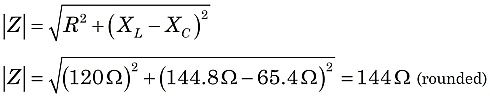
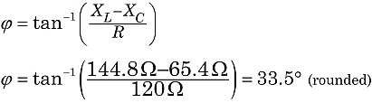
So, in this circuit, we would witness the effect of an impedance of 144 ohms, with the current lagging behind the supply voltage at a phase angle of 33.5°.
As you might guess from the discussion above, it is quite possible for the inductive and capacitive reactances to exactly cancel under the right combinations of L, C, and f values. That is a very important condition known as resonance.
4.21
- Understand the use of capacitors for AC coupling (DC blocking) and decoupling AC signals including radio frequency (RF) bypass to ground.
AC coupling
When connecting one circuit or stage in a device to the next, there are several things that need to be considered.
The connecting or coupling circuit must isolate all DC voltages to the part of the circuit they are required and not allow them to affect other stages.
The connection must have a bandwidth and frequency response that will permit the wanted AC signal to be passed but effectively filter out harmonics and any other spurious signals.
To ensure maximum power transfer the output impedance of one stage needs to be matched to the input impedance of the next.
Because capacitors block DC and pass AC they can be used to couple the AC from one stage to the next while blocking the DC biasing voltages.
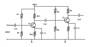
In the diagram we have two cascaded transistors acting as amplifiers. The biasing for T1 would affect T2 if it were not for Cc2 which is a coupling capacitor between the circuits of T1 and T2 and allows the AC output from T1 to act on the base on T2. Cc1 and Cc3 protect the previous and following circuits from the DC biasing voltages.
Decoupling
In a DC power supply line between stages, decoupling components are added to provide a path to earth for RF.
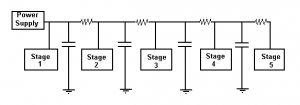
In the circuit above the capacitors to earth are 0∙1µF or less and provide a low impedance path to earth for RF currents while the resistors are low value (100Ω) and provide little voltage drop. Depending on the circuit requirements RF chokes (inductors) may be used in addition to, or instead of the resistors. This prevents RF from one stage entering another via the power supply line. This is known as decoupling the stages.