4. Technical Basics 1 - Mains Power to Ohms Law
4.1 Mains Power
- Recall the voltage and frequency of the mains supply used in Australia.
- Recall the voltages and relationship between the Active, Neutral and Earth in a single phase mains.
- Recall the colour code of mains wiring.
- Understand the reason for the Earth connection (if provided) on mains operated equipment.
- Recall the purpose of the fuse and switch being in the Active lead of mains operated equipment.
Mains voltage
In 1980, the International Electrotechnical Commission (IEC) rationalised the 220 V, 230 V and 240 V nominal voltage levels around the world to a consistent 230 V. This rationalisation was ostensibly made to improve the economics of making appliances by allowing manufacturers to produce a range of items with a rated voltage of 230 V. Not all countries have yet converted to the new standard.
The nominal voltage in most areas of Australia had been set at 240 V in 1926. In 2000, Standards Australia issued a system Standard AS60038, with 230 V as the nominal voltage with a +10% to –6% variation at the point of supply, i.e., 253 V to 216.2 V. A new power quality standard, AS61000.3.100, was released in 2011 that details additional requirements. The new standard stipulates a nominal 230 V, and the allowable voltage to the customer's point of supply is, as mentioned, +10% to –6%. However, the preferred operating range is +6% to –2%. (244 V to 225 V).
In Australia, the actual voltages delivered to customers is set at the state level. As of 2019, all states have transitioned to 230 V standards, with the exception of Western Australia and Queensland. Queensland began the transition to 230 V in 2017 and hopes to be completed to the "preferred range" by July 2020. The reason given for Queensland's decision to move was the increased use of grid-tied rooftop solar installations raising the grid voltage. By lowering the voltage to 230 V, additional headroom of 960 megawatts was created to accommodate future residential power generation from rooftop solar.
The voltage in New Zealand is also 230 V. In Fiji, Tonga and Papua New Guinea it is 240 V, and 220 V in the Solomon Islands. In China and Argentina the voltage is 220 V.
The AC frequency is 50 Hz.
Circuit conductors
Ground or earth in a mains (AC power) electrical wiring system is a conductor that provides a low-impedance path to the earth to prevent hazardous voltages from appearing on equipment (high voltage spikes). The terms ground and earth are used synonymously in this section; ground is more common in North American English, and earth is more common in British English. Under normal conditions, a grounding conductor does not carry current. Grounding is also an integral path for home wiring because it causes circuit breakers to trip more quickly (ie, RCD), which is safer. Adding new grounds requires a qualified electrician with knowledge particular to a power distribution region.
Neutral is a circuit conductor that normally completes the circuit back to the source. Neutral is usually connected to ground (earth) at the main electrical panel, street drop, or meter, and also at the final step-down transformer of the supply. That is for simple single panel installations; for multiple panels the situation is more complex. In a polyphase (usually three-phase) AC system, the neutral conductor is intended to have similar voltages to each of the other circuit conductors, but may carry very little current if the phases are balanced.
All neutral wires of the same earthed (grounded) electrical system should have the same electrical potential, because they are all connected through the system ground. Neutral conductors are usually insulated for the same voltage as the line conductors, with interesting exceptions.
Live or Active is a circuit conductor that delivers the supply current to a device.
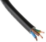
Mains wiring colour code
Brown = Live (old Standard Red for fixed wired)
As previously mentioned, the brown wire has the function of carrying electricity to the appliance. There will be a risk of electrocution if the brown wire is live and not connected to the earth or neutral wires. You must ensure that there is no power source connected with the live wire before working on the wiring.
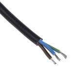
Blue = Neutral (old Standard Black for fixed wired)
The neutral wire colour is blue. The neutral wire transfers electricity away from the appliance to avoid overloading. It is located at the end of the circuit for connection after the electricity has flowed around the live and earth wires. It is highly unlikely that you will have an electric shock on contact with a blue wire. However, caution should be taken as the wire can run at a very high heat.
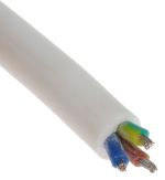
Green and Yellow = Earth
The earth wire colour now features green and yellow stripes. It has the key safety function of connecting the metal casing of the electrical appliance with the ground. This means that the current of the live wire cannot be directly transmitted to the casing. Contact with the protective earth wiring should not result in an electric shock but exercising caution is always recommended.
There should be some warning signage indicating installations featuring circuits and/or fixed cables and wires of mixed colours. This warning should be very clearly designated on either the fuse board or the consumer unit.
Earth connection
If there is a fault in your electrical installation you could get an electric shock if you touch a live metal part. This is because the electricity may use your body as a path from the live part to the earth part.
Earthing is used to protect you from an electric shock. It does this by providing a path (a protective conductor) for a fault current to flow to earth. It also causes the protective device (RCD or similar) to switch off the electric current to the circuit that has the fault.
For example, if a cooker has a fault, the fault current flows to earth through the protective (earthing) conductors. A protective device (fuse or circuit-breaker) in the consumer unit switches off the electrical supply to the cooker. The cooker is now safe from causing an electric shock to anyone who touches it.
4.2 Potential Difference and Electromotive Force
Fuse or circuit breaker
The fuse or circuit breaker must be connected in the live wire side of a domestic circuit to ensure that it keeps high voltage from reaching the user, or surroundings, if a fault develops.
In a mobile installation circuit breakers and switches are required to be double pole, meaning opening the live and the neutral conductor, because it cannot be guaranteed that the outside connection is of correct polarity.
- Understand the difference between potential difference (PD) and electromotive force (EMF).
- Understand the concept of source resistance (impedance) and voltage drop due to current flow.
- Understand the relationships between voltage, current, resistance and power. Calculate any one when any two other elements are known.
EMF - voltage
Potential Difference
For a potential difference (PD) to exist there must be an excess of electrons at one point and a lack of electrons at another point. It is the difference in potential between two points that gives rise to the force that creates a current flow when the points are connected. PD is measured in volts.
Electro Motive Force
Electro Motive Force (EMF) is the force created by a potential difference. It is the force created by a potential difference that causes a current to flow. EMF is measured in Volts and is often referred to as voltage. The symbol or abbreviation is E.
Eg. EMF = 5V or E = 5V.
Voltage
Voltage is actually the measurement of potential difference or EMF. One Volt is the PD or EMF required to create 1 Ampere of current through one Ohm of resistance.
Because PD, EMF and Voltage are so closely aligned the terms are often technically misused and interchanged.
Often a current source (battery or other supply) will be shown as V=12V rather than E = 12V. Similarly a resistor is said to have a voltage drop across it rather than a potential difference between either end.
Current
Current is the number of electrons moving past a point in a given time and has the symbol I. It is measured in amperes (A). I = 2A.
Note that current flows in all parts of a circuit at the instant the circuit is made (switched on). Like water in a pipe if you add water at one end, water immediately appears out of the other end because there is water already in the pipe. Current is the same. As an electron joins an atom it bumps an electron out of orbit in that atom to the next which has the same effect. It is the bumping effect that can cause a switch in Sydney connected to a light globe in Perth to light instantly when the switch is made.
Resistance - voltage drop
Resistance
Resistance is the opposition to current flow and has the symbol R. It is measured in Ohms and uses the Greek letter omega (Ω). R = 20Ω.
Voltage Drop
When ever a current is flowing through a resistance some energy is used to 'push' the electrons through the resistance. This creates a difference in voltage across the resistance, known as the voltage drop or Vd.
Ohms law
The Ohm’s Law Triangle
Every electrical engineer has seen the Ohm’s Law triangle at some point in their education. It’s the “go-to” for teachers when trying to help visually explain the formula. As a quick refresher, the triangle is a visual representation of the mathematical relationship between voltage (V, sometimes represented as U or E), resistance (R), and current (I) in a circuit. This triangle is an easy tool for new engineers to remember the three main aspects of electricity.
![]()
Ohm’s law triangle includes three sections: The top half must always be voltage. The bottom half is then split into two smaller halves for current and resistance – current is usually on the left with resistance on the right, but the order doesn’t really matter. It just seems that because most people remember the formula as V = I*R, they write it in the triangle as such.
To solve for one of the variables, cover the letter being solved for and use the remaining line separation to give you the mathematical expression. For example, when solving for resistance (R), cover the R and all that is left is V and I. Then use the line that separates those two variables as an indication to use division. The same is true when solving for current (I). The only tricky part is when solving for voltage (V); the line separating I and R then represents multiplication because the items are next to each other.
The three resulting variations of Ohm’s Law are:
V = I * R
I = V / R
R = V / I
This leads to easy manipulation of a circuit. For example, if resistance were to decrease in a circuit with the voltage held constant, the current increases.
In the end, Ohm’s Law is not very complicated, but it is essential for circuit design. If two out of the three values are known, the missing value can be easily calculated. The inner workings of every circuit, no matter how simple or complicated, rest on this cornerstone of electrical engineering.
4.3 Resistance
- Understand and apply the formulae for calculating the combined values of resistors in series and/or parallel.
Resistors in series
Resistors in Series
When resistors are connected one after each other this is called connecting in series. This is shown below. To calculate the total overall resistance of a number of resistors connected in this way you add up the individual resistances. This is done using the following formula: Rtotal = R1 + R2 +R3 and so on. Example: To calculate the total resistance for these three resistors in series.
 |
Rtotal = R1 + R2 + R3 = 100 + 82 + 1 Ohms = 183 Ohms |
Resistors in parallel
Resistors in Parallel
When resistors are connected across each other (side by side) this is called connecting in parallel. This is shown below. 
Two Resistors in Parallel
| To calculate the total overall resistance of a of two resistors connected in this way you can use the following formula: |
Example: To calculate the total resistance for these two resistors in parallel.
Three or more resistors in parallel
 To calculate the total overall resistance of a number of three or more resistors connected in this way you can use the following formula:
  Example: To calculate the total resistance for these three resistors in parallel
4.4 Resistance
- Identify the value and tolerance of a resistor using the resistor colour code.
Resistor Colour Chart
Four Band Resistor Colour Code
The Colour Codes used on resistors in carbon, carbon film and metal film types are widely used and a ‘must learn’ for electronics engineers. The tables on this page illustrate three common forms for four, five and six band resistors.
In the four band resistor colour code illustrated in Table 2.1.1, the first three bands (closest together) indicate the value in ohms. The first two of these bands indicate two numbers and the third, often called the multiplier band indicates the number of zeros, e.g. red, red, red indicates 2200Ω, which is normally called 2.2KΩ or 2K2. This last version is used in many circuit diagrams and suppliers catalogues (where print may need to be very small) to avoid 2.2K being read as 22K instead of 2K2 where the decimal point may not be obvious. The multiplier band will most commonly be some colour between black (no zeros), indicating a value between10 Ω and a value less than 100Ω, and blue (6 zeros), indicating a value in the tens of millions, e.g. 10,000,000Ω (= brown, black, blue)
Table 2.1.1 Four Band Resistor Colour Code
Two special cases of the multiplier band (band 3) are used for very small values where gold indicates that the first two bands must be divided by 10, and silver means divide by 100, e.g. 4.7Ω (or 4R7) would be indicated by yellow, violet(47), gold (divided by 10) = 4.7Ω.
The fourth band, separated by a space from the three value bands, (so that you know which end to start reading from), indicates the tolerance of the resistor. Gold (+/-5%) and silver (+/-10%) being the most common tolerances.
Notice also that where bands 1, 2 and 3 are black, this would signify a 0Ω resistor, which seems ridiculous as this would virtually be a piece of wire. Actually there is a reason that 0Ω resistors are available; the reason is that where a wire link may be needed on a printed circuit board, it is easier for automated component insertion machines to insert a 0Ω resistor that is the same size and shape as a resistor, rather than have to use another process to insert a wire link. Also this resistor can easily be changed for a different value where different versions of a circuit may be built, using the same PCB. The tolerance band on a resistor indicates the spread of possible values of any particular resistor, for example a resistor marked as 47KΩ +/- 10% will have an actual value somewhere between 42.3KΩ and 51.7KΩ
4.5 Potential dividers
- Recall that two or more resistors can be arranged to act as a potential divider.
- Understand how to calculate the values of resistors required to obtain a particular output voltage.
Potential divider
Ideal Voltage Divider
There are two important parts to the voltage divider: the circuit and the equation.
The Circuit
A voltage divider involves applying a voltage source across a series of two resistors. You may see it drawn a few different ways, but they should always essentially be the same circuit.
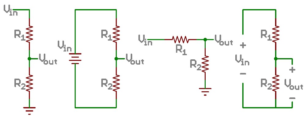
We'll call the resistor closest to the input voltage (Vin) R1, and the resistor closest to ground R2. The voltage drop across R2 is called Vout, that's the divided voltage our circuit exists to make.
That's all there is to the circuit! Vout is our divided voltage. That's what'll end up being a fraction of the input voltage.
The Equation
The voltage divider equation assumes that you know three values of the above circuit: the input voltage (Vin), and both resistor values (R1 and R2). Given those values, we can use this equation to find the output voltage (Vout):
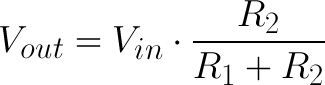
This equation states that the output voltage is directly proportional to the input voltage and the ratio of R1 and R2. If you'd like to find out where this comes from, check out this section where the equation is derived. But for now, just write it down and remember it!
Potential divider simplifications (optional)
Simplifications
There are a few generalizations that are good to keep in mind when using voltage dividers. These are simplifications that make evaluating a voltage dividing circuit just a little easier.
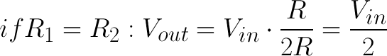
First, if R2 and R1 are equal then the output voltage is half that of the input. This is true regardless of the resistors' values.
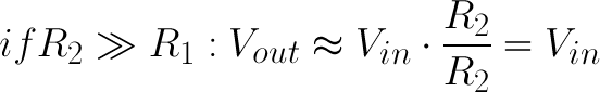
If R2 is much larger (at least an order of magnitude) than R1, then the output voltage will be very close to the input. There will be very little voltage across R1.
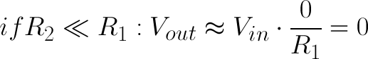
Conversely, if R2 is much smaller than R1, the output voltage will be tiny compared to the input. Most of the input voltage will be across R1