I am building an antenna tuner for a dipole made from screwdriver antennae based on an Arduino Mega. The requirement is to monitor the frequency of the connected radio and automatically recall position and matching information, and start the fine tuning process if required.
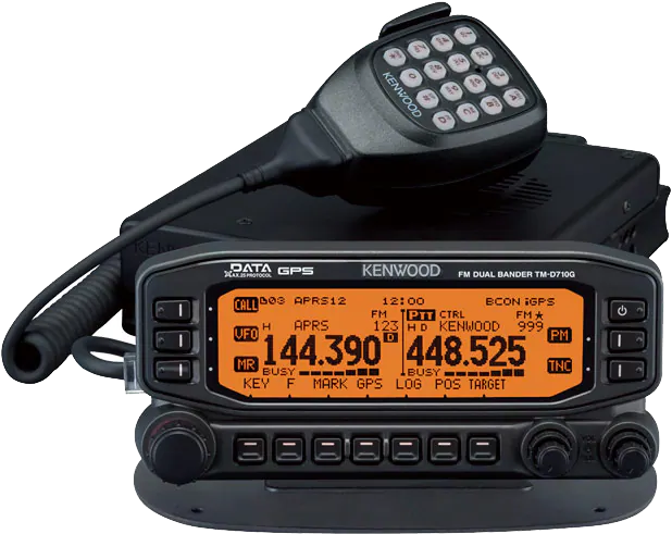
As part of this project I needed to connect the CAT (PC) connection of the Transceiver to an Arduino. I used the TM-D710 as an example although it is not the target radio for the tuner, which is a TS-480HX. However, I have two of the D710 and one in my lab/office, while the 480 is in my truck. So testing the hardware connection with the D710 was simply more convenient.
Once this was sorted I could move on to the connection to the HF radio, which is very similar.
There is next to nothing useful information on the web about this application. The commands can be found and gazillions of idiotic YouTube videos about CAT. Once you find something touching on the subject you find that they just missing the important bits of information. So here it goes in a systematic approach to solving the problem.
With this project description I assume that the reader is familiar with Arduinos and programming. This is not a beginners lecture, however, only little knowledge is required.
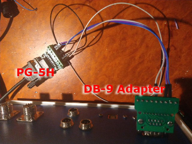
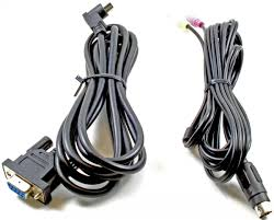
We first look at what Kenwood gives us to connect a serial device to the PC connector of the radio. The PG-5H cable set gives us a 8 pin to DB-9 connector cable, which we can use for the connection. (see image on the left). The other is a data cable for audio transmission, which we do not need for this exercise.
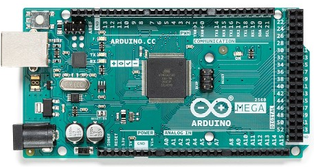
The Arduino Mega does not have a DB-9 connector to plug the cable into directly. So we need some gadget to link a DB-9 connector to the Mega.
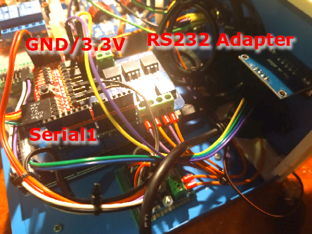
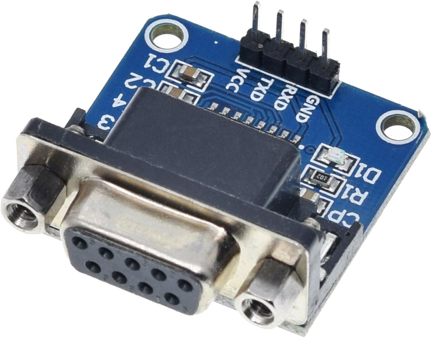
To the right one can see an adapter which uses a DB-9 connector and provides four output pins. There are different configurations readily available all based on the MAX232 chip, which converts the RS232 signal level (12V) to the Arduino TTL signal level (5V/3.3V). This is important otherwise we fry the Arduino ports. We can see that there are only TX and RX pins besides the VCC and GND pins, meaning there is no handshake (CTS,RTS) available. We get to that later.
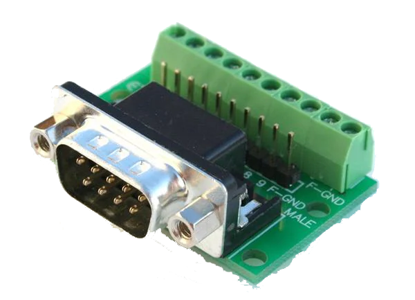
I use DB-9 connectors with screw terminals for temporary experimental connections. For final cables one would use connectors with a shell. This allows to make the connections easy on both sides and it also works as an adapter. The connection of CTS to RTS needs to be on the radio side. For permanent cables I suggest to make the connection on both sides.
At this point it is important to mention that the VCC for the adapter must be 3.3V from the Mega. DO NOT CONNECT THE 5V TO VCC - it will not work. This is info you will not find on the web at all, at least I didn't. One would assume that 5V would work since the Mega is a 5V device, but it does not. Took me a while to figure that out.
One could also use a RS232 shield for the Arduino, but I prefer the panel type adapter to mount on the rear wall of a box, which is hard with a shield.
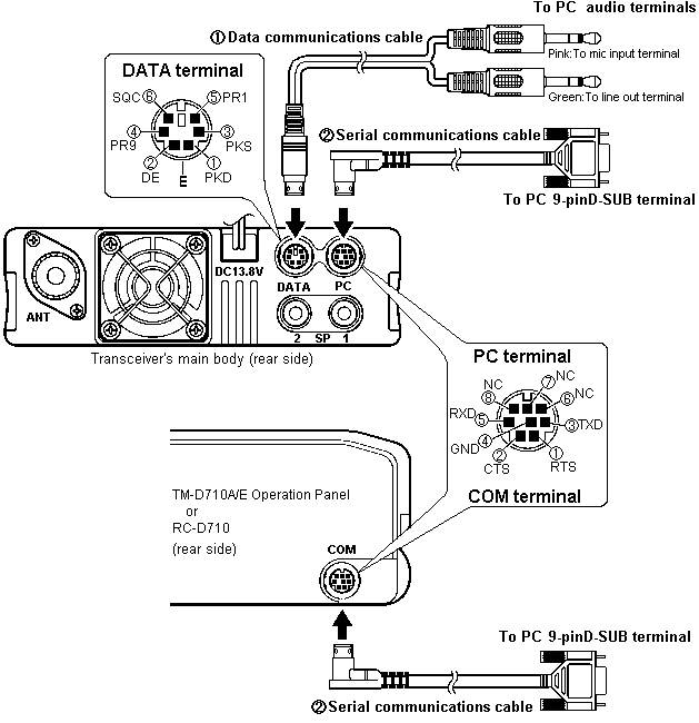
The image to the left shows the connecters at the back of the radio. The PC connector is what we need here with the DB-9 connector.
Now both sides are female and won't directly connect. A male/male adapter does not solve the problem.
The reason for this lies in the connection of the PC cable of the PG-5H.

First of all the TX and RX is crossed and the CTS and RTS are connected and used on the radio side. We need to make a cable which crosses RX/TX again and shunts the CTS/RTS to simulate permanent readiness to receive towards the radio. The Arduino is quick enough to do that without handshake.
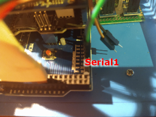
The last step is to connect the RX and TX of the RS232 adapter to the RX and TX pins of one of the Mega's serial ports. I used Serial1 for that. RX goes to RX and TX goes to TX, NOT CROSSED, this happens in the level converter.
Set the baud rate of the radio to 9600 for the PC board and everything is ready to go.
Here is a short sketch to read the VFO frequency of receiver B and poll changes,. which are displayed on the Serial Monitor of the Arduino IDE. The syntax of the command is:
XX[sp]Ncr XX = two letters for the command, [sp] = a single space, N = a parameter and cr = to end the command.
The command codes for the 710 are listed below.
This sketch will poll the radio every half a second for frequency changes and will display a new frequency on the Serial Monitor window. Very fast changes of a frequency knob may delay the response of the radio.
/* Kenwood TM-D710G
 * Read VFO Frequency of receiver B (Channel 1)
 */

byte message[5] = {'F', 'O', ' ', '1', '\r'};   // fixed message FO 1

char incoming[100];                             // buffer for incoming response
int count = 0;                                  // number of incoming characters

String frequency = " ";                         // Frequency value

void setup() {
  Serial.begin(115200);                         // Console output
  Serial1.begin(9600, SERIAL_8N1);              // Initialise serial connection with radio
                                                // no parity 1 start/stop bit
}
void loop() {
  char rc;                                      // single character for read
  Serial1.write(message, 5);                    // send message to radio
  delay(10);                                    // just wait a little, mostly not necessary
  count=0;                                      // start receive count
  while (Serial1.available() > 0 ) {            // if input available
    rc = Serial1.read();                        // read the character and buffer it
    incoming[count++] = rc;
  }
  if (count>0) {                                // in case we have input
    incoming[count] = 0x00;                     // terminate string with 0
    // split and isolate frequency
    char * partial;                             // partial strings for split
    partial = strtok(incoming, ",");            // split by ,
    if (partial != NULL) {                      // we have the first string
      partial = strtok(NULL, ",");              // we know frequency is the second entry after the ,
      if (partial != NULL ) {                   // if we have a frequency
        if (frequency != partial ) {            // if we have a new value
          frequency = partial;                  // store it
          Serial.println (frequency);           // and display on Serial Monitor
        }
      }
    }
  }
  delay(500);                                   // wait a bit to let the radio breath
}
## Available control commands for the display unit
(Firmware V1.04 TM-D710Gx, Firmware V2.15 TM-D710x)
These commands work with the display unit on the TM-D710 (and the TM-V71 when using the RC-D710 accessory).
- AE [Display serial number](/commands/AE.md) (This will display gibberish)
- BE [Enable/disable BCON - TMD710G](/commands/BE.md) (When APRS is enabled)
- BL [Backlight status](/commands/BL.md)
- CS [Callsign](/commands/CS.md)
- GP [Internal GPS - TM-D710G](/commands/GP.md)
- GT [Internal GPS](/commands/GT.md) Returns N if internal GPS is not on
- ID [Radio Model](/commands/ID.md)
- RT [Time](/commands/RT.md)
- SR [Reset](/commands/SR.md)
- TC [TNC control mode](/commands/TC.md)
- TN [TNC status](/commands/TN.md)
- TS [TNC control mode 2](/commands/TS.md)
- TY [Display Type](/commands/TY.md)
- 0M PROGRAM [Enters MCP programming mode](PROGRAMMING_MODE.md)
## Available control commands for the main unit
(Firmware V1.04 TM-D710Gx, Firmware V2.12 TM-D710x)
- AE [Radio serial number](/commands/AE.md)
- AS [Reverse](/commands/AS.md)
- BC [PTT and CTRL Band](/commands/BC.md)
- BT [Burst tone](/commands/BT.md)
- BY [Squelch open/closed](/commands/BY.md)
- CC [Call channel](/commands/CC.md)
- CD [Toggle between memory name and channel number](/commands/CD.md)
- DL [Dual Band Mode/Single Band Mode](/commands/DL.md)
- DM [DTMF memory](/commands/DM.md)
- DT [DTMF](/commands/DT.md)
- DW [Emulates the Microphone Down Key](/commands/DW.md)
- FO [VFO channel](/commands/FO.md)
- FV [Firmware version](/commands/FV.md)
- ID [Radio Model](/commands/ID.md)
- LK [Lock](/commands/LK.md)
- ME [Memory channel, frequency, offset etc](/commands/ME.md)
- MN [Memory name](/commands/MN.md)
- MR [Memory channel](/commands/MR.md)
- MS [Power on message](/commands/MS.md)
- MU [Menu](/commands/MU.md)
- PC [Output power](/commands/PC.md)
- PV [Programmable VFO](/commands/PV.md)
- RX [Receive](/commands/RX.md)
- SQ [Squelch status](/commands/SQ.md)
- SR [Reset](/commands/SR.md)
- SS [S-meter squelch](/commands/SS.md)
- TT [Transmit tone](/commands/TT.md)
- TX [Transmit](/commands/TX.md)
- TY [Radio Type](/commands/TY.md)
- UP [Emulates the Microphone Up Key](/commands/UP.md)
- VM [Memory/VFO](/commands/VM.md)
- 0M PROGRAM [Enters MCP programming mode](PROGRAMMING_MODE.md)
- 0G KENWOOD [Enters service mode](SERVICE_MODE.md)
Note: The first group is used when the cable is connected directly to the control head. The second is for the main unit. A downloadable file with all command details can be found at the groups below.
The above list was provided by:
# TM-V71 and TM-D710(G) Kenwood - PC RIG control commands
Reverse engineered RIG control commands for the Kenwood TM-V71 and TM-D710(G).
Thanks to: LA8OKA, W6GPS, WM8S and N1LKS for helping.
Based on rev.11 02 april 2009
## Contributing
Please report any errors or new information to the [issue
tracker](https://github.com/LA3QMA/TM-V71_TM-D710-Kenwood/issues).
## Additional information
- [TM-D710/TM-V71 mailing list](https://kenwood-radios.groups.io/g/main/messages) and (https://kenwood radios.groups.io/g/TM-D710-and-TM-V71)
The HF commands are similar, with a ; at the end instead of a cr. However, the functions are different and reflect the difference of a HF radio vs a VHF/UHF radio as well as some model specific codes.
This concludes the description of this project module. Some images of my actual application below.
