- Scope of document
Building an automatic antenna controller for two screwdriver antennae, mounted semi-colinear with facing mount points. Identification of required concepts, description and design of hardware and software components.
- Required functions/features
Hardware aspect
- a) Driving motors of each antenna with recognition of start and end position
- b) Variable motor speed for fine tuning of the antennae
- c) Counting motor revolutions when antenna is moving
- d) Measuring forward and reflected power for SWR calculation and automatic fine tuning
- e) Measurement amplifier for output of directional coupler with range switch for 0-200W and 0-2000W
- f) Tuning module with relays for matching capacitors when required
- g) Serial interface for CAT commands from Transceiver
- h) Second serial interface to relay CAT commands to amplifier if required
- i) Ethernet interface for remote control
- j) USB interface for firmware updates
- k) Serial interface for touch screen
- l) Parallel interface for keypad
- m) Touch screen for display and control
Software aspect
- a) Turn count and matching C memory (min, max) for each band, 160m, 80m, 40m, 30m, 20m, 17m, 15m, 12m, 10m
- b) Calibrate to 0 when power off at bottom
- c) Remember position when powered off
- d) Speed control for motor, slow for fine tuning
- e) Monitor motor voltage and stop motor power when at top or bottom
- f) Allow entry of turn count via keypad
- g) Manual control for each antenna (Up, Down, Park)
- h) Mode for single antenna and dipole antenna
- i) Store SWR for each band and tune when saved
- j) Store recent SWR for each band
- k) Separate memories for different whip sizes
- l) Seek function (slow motor) for each band
- m) Count range for seek function
- n) Web interface for stored value display
- o) Web interface for change of settings
- p) Web interface for remote control
- q) Reading band changes of transceiver via serial interface
- r) LCD display output for settings and value visualisation
- s) Touch display functions for manual control and display screen selection
Hardware components / modules
- Arduino Mega
- Ethernet shield
- Relay Board
- Display adapter
- SWR bridge
- 4D touch screen
- Foil keyboard
- Power supply, regulated 7V (Arduino)
- Power supply, regulated 12V (SWR Bridge)
- Power supply, regulated 5V (Display, other components)
- Power supply 6-12V with digiPot for variable motor speed
- Flip/Flop switch for momentary power button
- Measurement amp for SWR bridge output (2 channel op-amp amplifier)
- Current meter for motor drive current (2 channel – one for each antenna)
- Matching module with relays and capacitors for automated capacitive matching

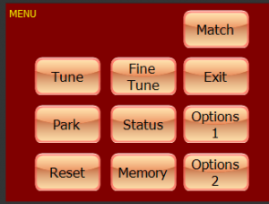
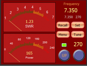
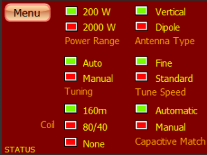
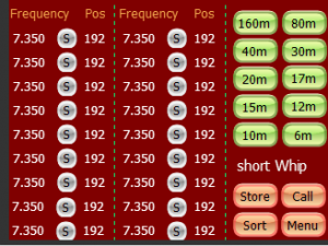
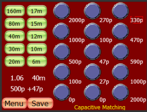
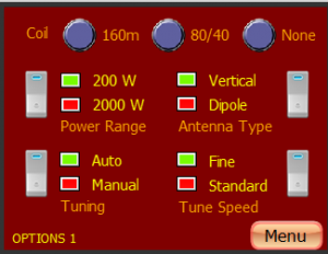
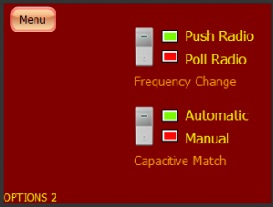
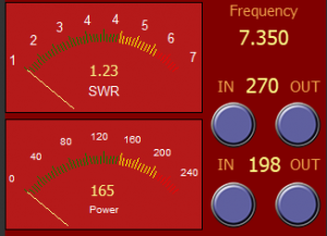
Display Screen Design
Some first designs for the 4.3" touch screen. Will be refined and extended.